The Redflow Gen3 ZBM

The Redflow Zinc-Bromine Module (ZBM) is the smallest commercially available hybrid zinc-bromine flow battery in the world. The size of these 10kWh energy storage modules means they can be deployed in applications, such as telco tower sites, that were previously impossible to address with flow batteries, yet they can also scale to grid-level energy storage.

The Redflow ZBM is a convention-breaking energy storage machine. It can be thought of as a miniature, reversible, zinc electroplating machine made largely of recyclable plastic. The innovative Redflow battery design uses abundant and relatively cheap minerals in its electrolyte formulation. These attributes gives the product strong environmental credentials. 

I recently spent some time at Redflow’s Brisbane headquarters taking a close look at the new Redflow Gen3 energy storage module. It is impressive to see just how far the Gen3 project has progressed in recent months and to appreciate the level of innovation it embodies.

Redflow has developed and optimised the design of its Gen3 battery in various stages during  the past five years, incorporating knowledge and optimisations based on field deployment of the Gen2.5 product. The Gen3 battery utilises the advanced manufacturing capability developed by the company in its own dedicated factory and delivers a streamlined product designed for reliable and high volume production.

The Gen3 ZBM is slightly smaller, and yet delivers the same baseline performance specifications as the Gen2.5 module. Gen3 is designed to be an easy, drop-in replacement for the previous model in any customer application.

Redflow initiated Gen3 customer trials at the end of 2020 and also undertook further lab testing of key components and complete new Gen3 batteries. This has led to further design advances in Gen3 flow distribution, management of shunt currents and software optimisation. The current expectation is that Gen3 will be introduced into production around the end of 2021.

This is what a Redflow Gen3 ZBM looks like:

Redflow Gen3 ZBM

It is time to take a look under the hood… and the more you look, the more improvements become evident.

This is a photo of some Gen2.5 batteries, for comparison, sitting beside a Gen3 battery undergoing testing at Redflow:

Gen3 battery beside some Gen2.5 modules

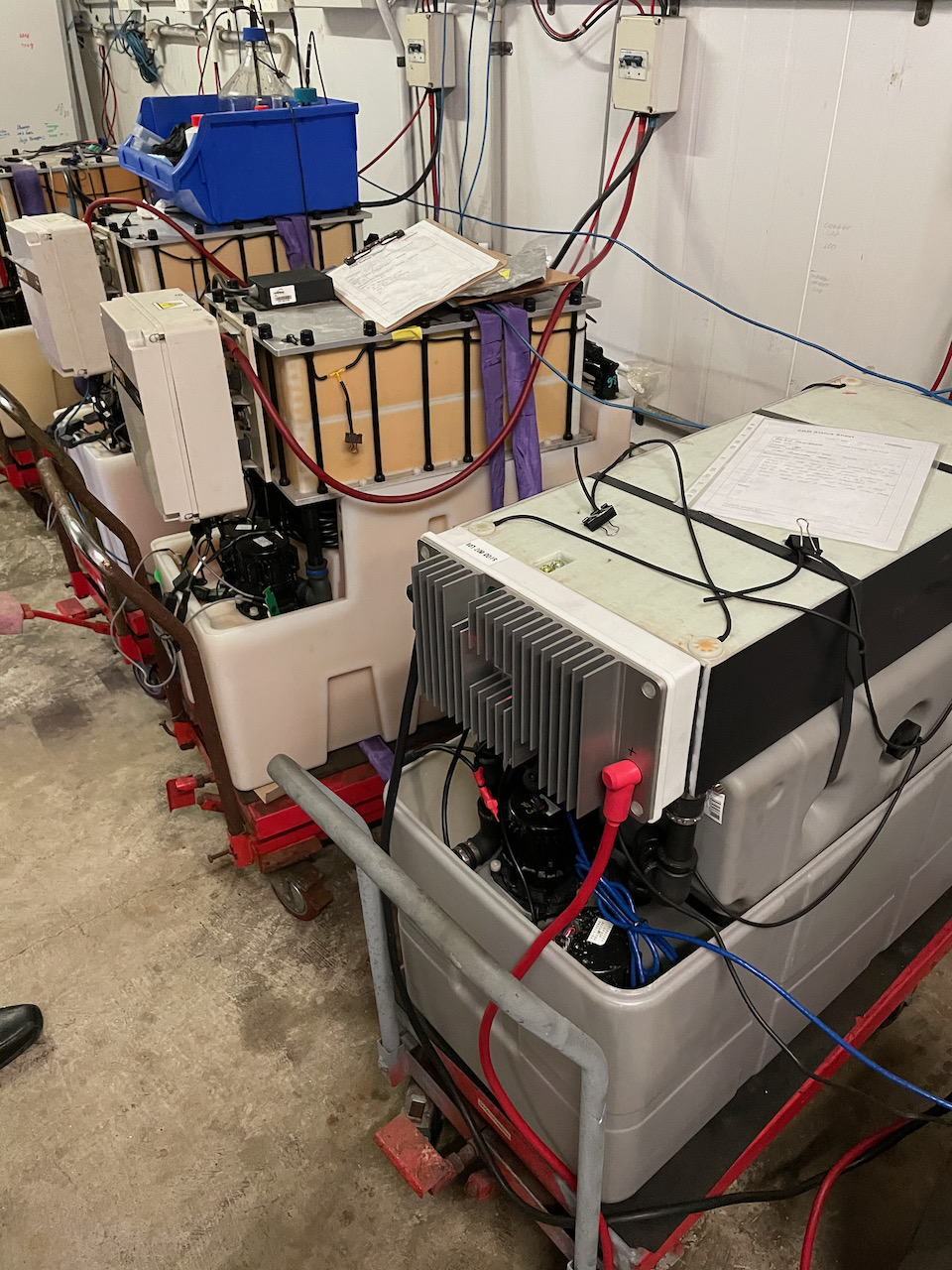
There are many improvements in Gen3, all designed to reduce parts count and cost while also making the product easier to manufacture.

Single Stack vs Dual Stacks

The key Gen3 improvements are related to the “heart” the device, the electrode stack.

This unique battery stack design, materials set and manufacturing system are where the majority of the Intellectual Property, Patents and Know-How developed by Redflow over the past 10 years resides. The new Gen3 stack represents a major step forward for the company in all of these respects.

This new product implements a single 10kWh stack at the top of the Gen3, replacing a pair of 5kWh stacks on the Gen2.5 model. Having just one stack instead of two delivers an obvious long-term reliability benefit.

That single stack also lowers production cost and reduces complexity in physical, chemical, and electrical terms. Redflow has also revised the internal construction of the new stack, including the fluid flow paths and the stack surface itself, for simpler and faster manufacture.

Gen3 Stack electrode plate layers ready for final assembly

This single stack design eliminates the need to wire the two stacks together in parallel with an adaptor plate on the front of the stack, reducing parts count and complexity.

Moving to one stack also removes the requirement to bind the two stacks tightly together with large metal plates and long bolts. The Gen2.5 requires these relatively costly structures to maintain a consistent electrolyte fluid seal and to manage consistent electrolyte flow across both stacks. In Gen3, none of that is needed

The single new stack is simply strapped on to the top of the battery tanks, making it easier to replace the stack in the future, if required.

Because the stack is also a major cost item in the ZBM bill of materials and is also a critical path item in manufacturing time, the single stack delivers obvious and profound implications in terms of increased peak factory production rate and decreased overall production cost.

New Electronics Module (MMS)

The Module Management System (MMS) – the electronics box on the front of the battery stack – contains power-handling and control electronics which are run by an on-board device management computer.

The Gen3 MMS has been totally redesigned, delivering both short and long-term benefits.

The Gen2.5 battery MMS contains several separate circuit boards, due to more than a decade of incremental development. Gen3 puts them all on a single, redesigned, higher performance board.

The Gen3 battery MMS also has battery terminals on the front of the unit, rather than ‘behind’ the MMS, which makes electrical interfacing a lot easier.

The Gen3 design eliminates the separate “Energy Extraction Device” (EED) sold with Gen2.5 batteries by building that functionality into the MMS as a software-controlled element.

The new MMS costs much less to make and is far more powerful in terms of CPU and I/O capability.

Advanced current flow management and software-driven bidirectional DC/DC conversion circuitry allows for the development of improved MMS firmware to deliver new software-driven current control and voltage control features, along with other planned improvements. These will be rolled out to customers through in-field software updates via the Redflow Battery Management System (BMS).

Other improvements in the new MMS Include the use of solid-state circuit-switching hardware based on Field-Effect Transistors (FETs) to connect, disconnect and mediate energy flow into each ZBM, versus the use of three physical ‘Contactors’ inside the Gen2.5 MMS. This eliminates some expensive moving parts from the MMS by replacing them with devices that are not only faster but that have an essentially unlimited cycle life in this application.

Redesigned electrolyte tanks, pumps, and cooling structure

The ZBM has two electrolyte tanks, each with its own pump. The Gen2.5 uses a nested, ‘tank within a tank” arrangement that, while elegant, is quite complex and expensive to make. Gen2.5 tanks are also constructed with many sharp corners and a complex side-wall design, making high volume manufacturing even more challenging.

The new Gen3 tanks are quite different. This is a picture of the new tanks with pumps without any other parts installed. You can see that there is a new plastic formulation and that they feature distinctly rounded corners:

tank

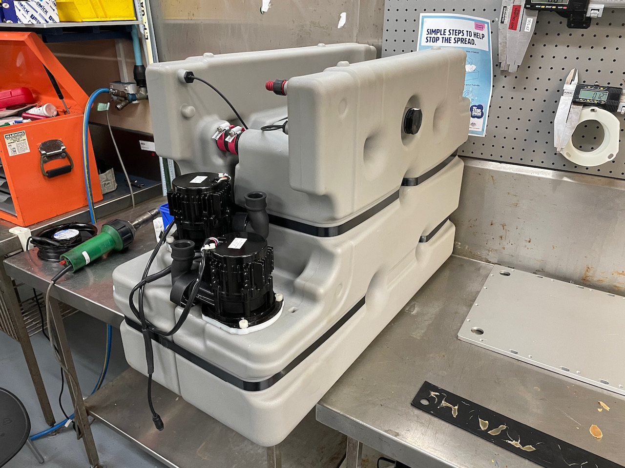
This is all designed to optimise the tank for volume production. This design is easier to build and has an increased tolerance for variation between tanks during the manufacturing process. The new tanks are also arranged as a simple left-right pair – much simpler than  the Gen2.5 nested tank structure, further improving ease of assembly.

The pumps have also changed. For historical reasons, the Gen2.5 pumps are actually 140 volt DC pumps that require a custom-designed voltage uplift circuit inside the MMS to drive them. The Gen3 pumps are 24 Volt DC pumps that can be more easily and efficiently driven from the MMS.

As part of the new Gen3 design, Redflow is also introducing a new cooling system using a new set of Filtering Polymeric Fibrous materials which will improve battery performance.

All up, the new tank cooling system and pump set represent a major improvement, designed, like the rest of Gen3, for repeatable high-volume manufacture at a lower production cost.

Purpose-built electrolyte ‘bund’

In many markets, energy storage devices that use fluid electrolyte in field deployments need to include a ‘bund’ – somewhere to catch and hold electrolyte fluid in the unlikely event of a fluid leak.

For the Gen3 battery Redflow has a new purpose-built bund. This is the plastic enclosure extending to about halfway up the battery on all sides, that is visible in the lab test photo above.

The intention is to ship Gen3 batteries with this bund included, saving installers the need to arrange and install a separate bund.

Gen3 Summary: Greater reliability, lower cost, faster production

The Gen3 module marks a major transition for Redflow.

Gen3 is designed for volume manufacture, with a design emphasis on fewer parts, greater ease of manufacture, and more compatibility with automated production techniques. By intent, this all leads to a lower production cost and greater long-term reliability.

These improvements benefit both Redflow and its customers as the company moves to ramp production volumes to meet the rapidly expanding global demand for scalable, sustainable and reliable energy storage.

Pod Z: The Redflow Grid-Scale HVDC Energy Pod

Simon Hackett, Redflow System Integration Architect

introducing Pod Z

Redflow is in the midst of building a new “Pod” based energy storage architecture, with the first customer for that deployment also being its largest customer to date.

The story below includes a link to a short video about the new architecture Redflow has designed to support entry into the Grid-Scale energy storage market:

Redflow Pod Z grid-scale architecture using Trumpf HVDC modules

When we made that video, we hadn’t formally announced our partnership with TRUMPF Hüttinger, the company we’re working with to deliver this scalable architecture. A few days later, we were able to make that announcement:

How Does Pod Z Work?

Now we’ve made that announcement, I can explain how this nifty stuff works.

Here’s a photo of a Redflow Pod Z with some of the covers taken off:

Redflow Pod Z internal elements

On the left is the battery cabinet with one of four covers removed. This cube-shaped cabinet holds 16 x ZBM2 storage modules, 8 to a side.

Ventilation paths run inward at the base of each pod. Air flow then rises via a ‘cold aisle’ in the middle of the pod, proceeds through each ZBM2, and exits as warmer air via fans installed behind each cover door.

While the Redflow modules you can see here are the existing Redflow ‘Gen2.5’ devices, the upcoming Redflow Gen3 modules will also be a perfect fit, in both physical and electronic terms (and they are designed to be).

To the right is the electronics cabinet for the pod. Inside that cabinet, at the lower right, is a cluster of six Trumpf DC1010 units with a Trumpf System Controller.

The DC1010 module achieves something quite special. It is a bidirectional DC/DC converter that can shift voltage up to a very high ratio (around 15:1).

These modules are clustered together and driven in a unified manner via the the system controller.

On the the low-voltage side, these modules interface to a standard 48V telco standard voltage bus (compatible with Redflow ZBM2 modules).

In fact, beyond merely being ‘compatible’ with Redflow ZBM2’s – the Trumpf product has been specifically designed for flow batteries!

This product line has been created by Trumpf in response to the rising demand for the use of flow batteries in large energy systems.

Flow batteries are long duration, 100% depth-of-discharge, durable and high-temperature-tolerant workhorses. They compliment, rather than conflict, with the use of shorter-duration/higher-peak-output capability Lithium batteries.

Trumpf have developed this product line at a time and in a manner that is an ideal complement to Redflow energy storage modules, and that paves the way to create grid-scale hybrid deployments that include flow batteries.

Flow battery support in the DC1010 includes a capability to have the low voltage DC bus operating all the way down to zero volts. The units then support smoothly raising the voltage of a flow battery back up to its normal operating voltage range, smoothly ramping a current-limited/current-controlled energy supply to the modules, as part of commencing the next charge cycle.

The DC1010 modules are each rated at 200 Amps continuous on the low voltage bus, meaning that this cluster of six units can support up to 1200A on that bus.

In the first Pod Z configuration, Redflow has rated each pod at a nominal continuous energy throughput of 50kW.

The low voltage bus comes together on the left hand wall of the control cabinet. On that wall is a pair of DC bus-bars sandwiched around insulation layers, with built in ‘comb’ connectors that allow the battery circuit breakers to bolt straight on to the bus-bar.

A set of 48V bus cabling (visible on the left hand wall) fans out from the bus-bar to all 16 batteries on the left, and additional cables run down to the DC1010 cluster at the lower right.

On the high voltage side, the DC1010 units support a (software selectable) interface voltage in the 765-900 Volt range.

On the lower part of the rear wall, you can see the output side cables for the high voltage side. Those (small!!) wires run at circa 800 volts and come together to the high voltage interface terminals. At a 50kW power level, across six DC1010 units, at (say) 800V, the current being carried from each of the cluster modules is a mere 10 amps (50,000 / 6 / 800). This is why those wires are so small – because they really don’t need to be larger.

This is one half of the key to grid scale battery deployments. That high DC voltage means the total cable size – even for a DC bus visiting many Pods in parallel in a single site – really isn’t all that large.

The other half of how this architecture supports high scale deployments is the way that voltage management happens on that high voltage DC bus. We are operating these modules in a mode that Trumpf call ‘Voltage Static Mode’.

In this mode, the DC1010 cluster converts the variable ‘48V rail’ DC voltage into a fixed voltage outcome on the high voltage side. All the pods are programmed to have the same HVDC voltage when idle, and they are just wired together in parallel.

To connect the DC pods to an AC energy grid, third party AC inverter/chargers are used.

When those inverter/chargers wish to discharge or charge from the overall Pod array, they simply ‘pull’ or ‘push’ against that DC voltage. If the inverters try to discharge, they naturally draw the DC voltage down in the process. The external draw-down on the DC rail acts as an automatic signal to the DC1010’s to start to deliver output energy. The amount of energy they deliver is proportional to the voltage shift that the inverter/charger initiates on the DC bus.

In the reverse direction (array charging), the inverter/charger drives the DC voltage up, and the DC1010’s respond to this by moving energy from the DC rail into the Pods. Again, the amount of current that flows is controlled via the voltage shift that the inverter/charger initiates.

Here is a diagram showing this result, just to make it clear (taken from the Trumpf system documentation):

The deep point of this operating mode is that each pod acts like an ‘ideal’ battery on the HVDC side, that:

  • always sits at the ‘perfect’ voltage, waiting for work to do
  • can be wired to an arbitrary number of similar pods
  • can be wired to, and commanded by, inverter/chargers

… all using the chosen DC link voltage – and shifting of that voltage – as a command mechanism that requires no software interface and no real-time cluster synchronisation for it to work.

In the initial deployment site there will be twelve pods sitting in rows on concrete plinths, delivering 600kW throughput via 12×16 module pods, for a total of 192 Redflow ZBM2 modules on site:

Deployment arrangement using 12 x Pod Z modules

Meantime, back inside each Pod Z, the Redflow ZBM2 modules are coordinated and controlled by Redflow’s purpose designed BMS, operating in a cluster-friendly ‘Slave’ operating mode.

Each Pod Z’s BMS:

  • Drives the Redflow ZBM2 module operating cycle internally in each pod, including coordinated maintenance cycles for batteries at appropriate times
  • Actively controls the operation of the Trumpf equipment cluster using a newly developed Trumpf operating module in the BMS. This code sends continuous updates via MODBUS-TCP to the Trumpf cluster, keeping it informed about the present operating limits of that particular cluster of ZBM2 modules. The key parameters sent are the maximum charge capability, maximum discharge capability, and the target charge voltage for the ZBM2 cluster.
  • The BMS provides secure remote management access to the Trumpf system controller and manages the high level configuration of the pod (including setting the HVDC operating voltage and current limits in Voltage Static Mode).
  • The BMS also watches over the Trumpf cluster, monitoring and logging operating parameters including voltage, current, and three temperature measurement points inside each DC1010 cluster member

With each Pod Z being fully managed by its internal BMS, all that remains is to aggregate the status of all Pods together, for the benefit of, and the coordination of, the on-site inverter/chargers and on-site Microgrid controller.

A Redflow BMS operating in in ‘Master’ mode is interfaced over ethernet to all the downstream Slave BMS in each Pod Z that it watches over.

The Master BMS passes overall status data to the on-site microgrid controller. This includes System State of Charge, overall site charging and current discharging capacity, temperature, and state of health. This information is provided via industry standard CANBus ‘Smart Battery’ protocol, MODBUS-TCP, and/or JSON queries to the Master BMS.

Summary

The Redflow Pod Z architecture has been designed with, and around, the Trumpf ‘TruConvert’ DCDC power system architecture.

The combination creates a powerful, integrated high voltage energy storage system that can be scaled to an essentially unlimited extent.

The interface mechanisms being used allow the high energy, high voltage Pods to be parallel-wired without complex or difficult real-time synchronisation or balancing mechanisms. Instead, the software-mediated Trumpf cluster creates a ‘perfect’ battery voltage for every Pod, driving the simplest possible integration path for high scale site designers.

The Redflow BMS acts as a per-Pod orchestrator for the Redflow ZBM2 modules downstream, and as a coordination and control point for the Trumpf DCDC converters in each Pod, and passes aggregated energy storage status data upstream to the on-site master Microgrid controller.

This architecture plays to the strengths of all of the components concerned. It is is designed for reliability, redundancy, and scale.