KNX Tips and Traps Part 2: KNX/IP Routing

This post documents my learning curve around the difference, in the KNX world, between a KNX/IP Interface, and a KNX/IP Router.

KNX terminology in this context is very important to understand. In part because this is a case of words (really) mattering, and in part because not only do the words matter, but their meaning also differs substantially from the meaning of those works in the pure TCP/IP networking context.

We will start with something that took me multiple product purchases and many hours of head-scratching to appreciate:

A KNX/IP Router is also a KNX/IP Interface

A KNX/IP Interface is not also a KNX/IP router

What is a KNX/IP ‘Interface’?

A KNX/IP ‘interface’ is any device that ETS5 can use to program your KNX devices over your local TCP/IP network from a Windows PC and/or that can allow KNX twisted-pair (TP) device access and control with apps/touchscreens/etc from the local TCP/IP LAN.

However, if a KNX/IP product does not explicitly use the word ‘Router’ in the product name, it is not (also) a router and will not provide KNX/IP routing.

What is a KNX/IP ‘Router’?

In KNX parlance, what a KNX/IP ‘router’ actually provides is the functionality of a KNX ‘area coupler’ or ‘line coupler’, using a TCP/IP network as the linking medium.

An area coupler or a line coupler is a packet forwarding bridge (with built in packet filtering) that moves KNX telegrams (packets) between KNX physical network segments.

The distinction between an ‘area’ coupler and a ‘line’ coupler is simply based on whether you are inserting the coupler (‘router’) to connect distinct areas (first number in the Individual Address is different) or just between distinct ‘lines’ (where the area number is the same but the ‘middle’ number differs).

In either designation, appropriate KNX ‘telegrams’ (packets) get forwarded to the other network segment if they need to be, and they are ‘filtered’ (not forwarded) if they don’t need to be.

Normally this process is automatic, provided you have given the KNX/IP router the appropriate form of Individual Address (IA) to tell it how it is supposed to act (more on this later).

In writing this down, I will say that it is no wonder this is confusing to people already steeped in the terminology and operation of TCP/IP networks (as I am).

It turns out that a KNX/IP ‘router’ is not really a ‘layer 3’ router at all. It is ‘merely’ a layer 2 media bridge. The fact that there is a routing-capable TCP/IP protocol stack inside every IP enabled KNX device doesn’t magically make all those devices into KNX ‘routers’.

One thing that would love ETS5 to feature (and it certainly doesn’t, today) is the addition of a dialog box to warn you about the absence of any configured-in area or line couplers in your setup, any time that you try to construct a group address that spans areas or lines in your project. It seems to me that a simple warning (“No configured area or line couplers are available to forward this telegram”) would save a heap of future grief for others.

Time to look at some real world product examples.

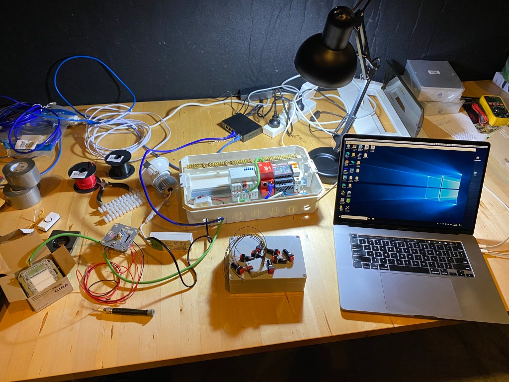
Here are some devices in my home KNX network:

Per the discussion above – only one of these three (the one on the left) is a KNX/IP router, despite all three boxes having more than enough technical ‘grunt’ to be capable of ‘routing’ (and for all I know, they might well all be running identical underlying hardware).

If you don’t have the KNX/IP router there (and at first, I didn’t), then the twisted pair segment concerned is an island. It doesn’t matter how grunty or wonderful your KNX/IP interface products are (the X1 and S1 are both highly capable things)… neither of those is going to route a group telegram between the TP and IP networks for you, no matter how much you try to convince it to do so.

It was the Gira S1 that drove my initial confusion, ironically because it is such a cool and capable device in other ways. Based on my historical TCP/IP experience, I’d thought that because the S1 is a remote-access VPN and local area TCP/IP node, it would also be a KNX twisted pair router – I mean.. why not? Well… no, it doesn’t do that.

One confusing thing is that even if your device isn’t a router, ETS5 will still let you manually define a filter table for it, when there is absolutely no (obvious) point! That is how ETS5 helped to cement my (mistaken) belief that my Gira S1 was a KNX/IP router, when it wasn’t.

I wasted a good day fiddling about, trying to work out why the thing wouldn’t send packets over the network, adding in manually added filter table entries for the group telegrams I wanted to forward and it just … wouldn’t. No error message, no sign of problems, just no packet forwarding. It is obvious now, but it surely wasn’t obvious to me up front.

How to buy the wrong product without really trying

Here are three more KNX devices, all of which are KNX/IP interfaces:

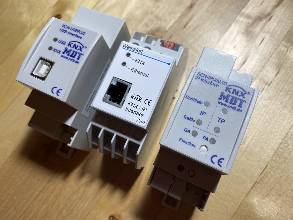
The unit on the left in the photo above is a USB-KNX interface, allowing ETS5 programming without any IP components in the system. The other two units are different brands of KNX/IP interface, and they are functionally identical. They can be used for programming KNX devices in your project over your local TCP/IP network, and/or for facilitating access to KNX TP devices from other TCP/IP applications.

I bought the right hand unit (the MDT one) after I realised the Weinzierl product (installed many years ago, with my underfloor heating system) was not a router. When I did buy the MDT unit to replace it (so I could start doing KNX/IP routing), I mis-ordered it.

MDT make two products with a one digit difference in product ID code:

MDT IP Interface and IP router product codes

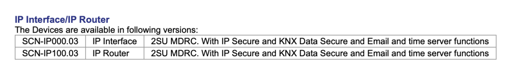
I purchased a 000.03 and I should have purchased a 100.03. The extreme similarity (in specification and visual appearance) underscores that they are most likely the very same physical box, sold at two different price points, where the lower cost one has simply got the KNX/IP ‘router’ functionality switched off.

Your choice of KNX/IP router Physical Address controls the functionality of the device!

This was a huge part of my learning curve, and not fully understanding this drove a lot of confusion for me in the first instance. In a TCP/IP network, the IP address is irrelevant to the functionality of a device. In a KNX/IP network, the Physical Address you chose has a dramatic impact on what your device will actually do.

The table (below) – or a variant of it – is a familiar component of the setup instructions for any KNX/IP router (this one is extracted from the startup document for a Gira KNX/IP router):

The mapping between Physical Address and device function for a KNX/IP router

If you do not assign a ‘.0’ as the last part of the IA for your router, then it will not operate as a router at all. If you chose to use an address ending in ‘not 0’, then your KNX/IP ‘router’ will only function as a KNX Interface and will not forward (route) KNX telegrams!

This is in fact a very good design decision in the KNX architecture.

If only a device ending in ‘.0’ can act as an area or line coupler, then you can never have more than one active KNX/IP router per physical twisted pair network segment. This is a good thing, as it ‘naturally’ avoids all sorts of complexities that occur in the TCP/IP context (including the need to implement a network routing table, versus a bridge filtering list).

Just to labour that point slightly – the absence of a layer 3 routing table in KNX is why what KNX does, in my view, is really layer 2 bridging, not ‘routing’. I think these really should have called these things KNX/IP bridges or even better, KNX/IP ‘couplers’ (but… ‘too late now’ 🙂 ).

As another aside: The use of IP Multicast to carry KNX telegrams on the IP side of this process is a smart one. This nicely leverages the merits of IP multicast to ensure carriage of those telegrams (‘packets’) to any other KNX/IP routers that need to hear them, without any explicit configuration work being needed on the TCP/IP ‘side’ of the equation.

Clues to help you to realise your KNX/IP device is not really a router after all

ETS5 is slightly maddening at times, in that it ‘knows’ things about your devices that it doesn’t bother to mention to you – assuming you just ‘already know’. A key one here being whether the thing you (wrongly!) believe to be a KNX/IP router is really just a KNX/IP interface after all.

In other words, ETS5 ‘knew’ full well that I bought the wrong MDT device (see above), and it kinda-sorta tried to tell me this, in ways that were too subtle for me to notice them at the time.

So – to save you the same angst here are the clues to help you know when your KNX/IP router is really not a router after all (i.e. when you ordered the wrong product):

Clue: ETS5 refuses to let you assign a .0 address to your device

This is a dead giveaway (in hindsight). ETS5 ‘knows’ full well its not a router, so when you try to set the last byte to ‘0’, it renumbers it to ‘1’, despite your best efforts to talk it into the ‘0’ at the end.

Annoyingly, not error message – ETS5 ‘should’ (in my view) pop up a message to tell you that ‘Only KNX/IP routers can be assigned an address ending in 0’. Instead, the address box turns red, and then turns black again after ETS5 silently ‘fixes your mistake’ (instead of telling you about it).

Clue: The ETS5 right-click menu on your device doesn’t contain ‘Preview Filter Table’

I finally figured this one out… if you right-click on a device and the pop-up menu contains “Preview Filter Table” then you are looking at a properly confgured-in-to-your-project KNX/IP router (i.e. area or line coupler):

KNX/IP Routers have “Preview Filter Table” on the menu. Non routers… do not.

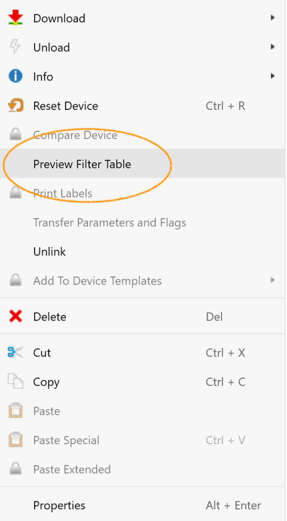
If you think you have got your router configured in properly but that “Preview Filter Table” entry is mysteriously missing when you right-click on it, then… you haven’t actually got it in there properly after all.

It would be really nice if KNX flagged a validly configured KNX/IP router more clearly on the device display. Displaying the device name in green or… something.

Clue: You can check if a KNX device is really a router before you buy it

ETS5 knows whether a device is a router or not. And it knows this based on the product catalogue, not based on your real physical device.

This is a subtle but important point.

You can select any device in ETS5 out of the global KNX product catalog, load it into your project, and use the earlier subtle clues (above) to assure yourself that it really is a router, and that it really will route… and then you can go buy it.

I wish I’d appreciated that before I started buying things!


KNX Tips And Tricks Part 1: VMWare, Dongles, and Scene Teach-In

The Back Story

I want to deploy KNX in some existing and new buildings. KNX is something I’ve been interested in learning ‘how to do’ for ages. Finally a good intersection of time and opportunity has lead to this being the right time for me to undertake the learning journey.

In the COVID era, I couldn’t easily attend the hands-on physical accreditation training courses in KNX design and deployment that are offered by the very fine people at IvoryEgg. So, instead, I started with a free KNX intro seminar they delivered online..

Next, I did the short online ‘eCampus’ introductory course at the knx.org site to get a high level understanding of how to drive the ETS5 app (and I will say that it was indeed very useful for that purpose).

Following that, well, I just licensed ETS5, bought some KNX gadgets from IvoryEgg, and started to just ‘figure it out myself’ because, to borrow the classic geek thought bubble:

How hard can this be?

The answer is that its not too hard, really, except that in doing it this way I’ve missed out on plethora of small nuances (especially about how to drive ETS5, and in how KNX concepts map to ETS5 reality).

These pieces of missing knowledge and understanding would have been gained by doing a formal hands-on training course. Without that, I found myself repeatedly in the situation of knowing something can be done in ETS5/KNX, but being unable to figure out in the first instance how to do it.

I felt that there may be some merit, for others, in writing down the non-obvious things – and their solutions – as I go along. Hence this blog post (and any others that may follow).

What is KNX?

KNX is a remarkable thing. It is a 30+ year old, published and standardised, protocol for building automation. It includes a standardised set of mechanisms for physically wiring and installing KNX-speaking devices in a building. More than 450 hardware vendors with guaranteed interoperation.

There is one ‘master’ programming tool (“ETS5”) that is used to program/configure and deploy KNX devices in real world environments. It imports definition databases and applets from each manufacturer, on demand, to support the myriad variations offered by each device, in a (moderately) consistent manner.

Now, lets start looking at the tricks and traps I have encountered on my self-taught journey into the wonderful world of KNX and ETS5:

Using ETS5 on a Mac: Making it work with VMWare Fusion

ETS5 is Windows software. I use a Mac.

I am running ETS5 on Windows 10 by using VMWare Fusion, which turns the Windows environment into a window on my Mac. This works really nicely with one particularly frustrating and non-obvious trap, related to ‘Network Settings’.

Out of the box, VMWare Fusion configures the Windows virtual “Network Adaptor” using NAT. This means that your windows instance has no direct TCP/IP connection to your Mac, but rather that it is sharing the IP address that your MacOS system uses.

Far from being a good thing – with ETS5 this is a very bad thing.

That’s because ETS5 relies on being on the same physical LAN segment as any IP-connected KNX devices (KNX ‘Interfaces’) that you want to use.

If you leave the VMWare environment set up using VMWare’s internal NAT then ETS5 cannot ‘see’ any of your TCP/IP-based KNX access devices at all – it is as if they just don’t exist.

You can’t make them turn up on the ETS5 interface selection page.. nothing works. Even worse, there are no error messages to help you figure out what is going on, either.. its just that nothing works as expected. 

Fortunately, the solution is simple.

In VMWare fusion, go to the Network Adaptor settings for the Windows instance, and change it to use ‘Bridged (Autodetect)’ instead.

That is all there is to it! Now your Windows instance reaches out and obtains its own TCP/IP address on the LAN, and it now has distinct (and direct) network identity. Now, it can see the LAN environment properly including (in particular) the IP Multicast packets that KNX relies upon, to work properly.

Fire up your ETS5 software again, and now all your KNX interface devices magically autodetect and work as expected. Win!

The only other thing of operational consequence in terms of using VMWare Fusion to run the Windows instance you need is that you need to plug the ETS5 license dongle into the Mac after activating my windows instance in VMWare Fusion, or it doesn’t ‘see’ it in ETS.

At worst (or if you forget), just unplug and re-plug the device after launching ETS5, and ETS5 will re-scan and notice the device soon afterward (no need to quit/relaunch ETS5).

How to avoid losing the (tiny) dongle

The ETS license is implemented via a physical USB Dongle. I have some issues with that dongle.

Iit is tiny, the same size as those little plug-in wireless keyboard dongles. This is something I hate – because a software license worth thousands of dollars shouldn’t be deployed in something that is so very easy to lose!

(Note that if you do lose the dongle, you can get it replaced for a moderate re-issue fee – but – why make it so easy to lose the thing and suffer financial cost and replacement delay in the first place?)

The ETS dongle uses a conventional USB-B plug, and my Mac is 100% USB-C. Given how expensive the license (and hence dongle) is, I have no qualms about dedicating an Apple USB-B to USB-C adaptor for the exclusive use of the dongle.

Because of that, though, I can’t leave it plugged in to my Mac all the time.

When you license ETS5, the KNX association sends your dongle in a lovely little presentation box. The box is made of sturdy cardboard material with nice printing on it, and the dongle sits inside, in a little foam bed. Very swish.

This box is big enough that I can put it in the accessory pouch in my laptop bag without losing it. Having to open that presentation box and clip the dongle into the Apple USB-C adaptor to use it, and then having to take it all apart again after each use, was painful. I lived in fear of the dongle getting detached from the adaptor and being lost.

This lead me to a pragmatic solution to the issue of the thing being too small.

What I did was to cut out a little hole in the end of the cardboard presentation box, plugged the dongle into the USB-C adaptor, closed that into the box and taped it shut (and wrote my name and number on the back).

In effect, I have created my own ‘super size’ and natively USB-C version of the ETS dongle, that is much harder to lose! This makes it much, much easier to find (and harder to lose down a drain) versus dealing with a little green dongle the size of a coffee bean.

Make a test bench to play with

It is very worthwhile getting a selection of real KNX devices as soon as you can, and starting to play. Here’s a photo of my home test bench at an early stage of my own exploration’:


What I did soon afterwards was to segment my KNX environment between that test bench and some pre-existing KNX equipment that was installed into my house some years ago by someone else (to implement an underfloor heating system). I segmented it using KNX/IP routers (more about those in a later blog post).

This means my test bench can be turned off and on, or futzed with in general, without breaking the production environment in the house. However, because I am using a couple of KNX/IP routers (one in the production setup, and one on the test bench), I can still reach back and forth between the deployed hardware and the test bench to try things (e.g. making a switch on my test bench drive a real world gadget somewhere else in the house).

Understanding ‘Scenes’

Scenes are an excellent concept in KNX – and it seems to me that driving rooms (and outcomes) via scenes is much more rational than having a forest of individual light switches and/or dimmers, even if all you are adjusting is lighting.

That said, once you realise a scene can drive outcomes across multiple types of actuators at once (lights, climate control, blinds, locks, audio systems, you name it)…that is the real lightbulb moment, starting as simply as the notion of having one button at the building exit labelled ‘Home/Away’.

There’s a key (and quite useful) concept related to scenes, called “Teach-In”. More about that later.

The ETS menu structure device Parameter configuration and adjustment is highly dynamic – sub-menus come and go depending on other menu selections

The Theben TA x S binary input device (you can buy them in various values of ‘x’, e.g. 2 4, 6 or 8) is a great device.

This was the first device I tried to get the hang of configuring using ETS5. When I started trying to do that, I just could not work out how to send anything but binary (single bit on/off) outcomes from it.

What I really wanted to do was to make a row of buttons that are ‘scene selection’ buttons. I made up a nice metal box with a row of pushbuttons on it, I wired them into a TA 4 S unit, and I set out to make each button select a scene number (1 through 4).

In the first instance, when I tried to program it in ETS5 – moving to the “Parameters” tab for the device – I just could not work out how to send a scene number with this device.

“Out of the box” the unit let me drive the switches as binary devices (one bit per input) only. It has lots of flexibility about how that works (in terms of whether the bit sent represents absolute switch position or a toggling value, various de-bouncing parameters, etc etc). All lovely, but I wanted to send scene numbers, and they were just absent from the menu structure entirely.

Finally I figured out the subtle quirk (in my view) of the ETS5 interface, and it is this:

When you are looking at a Parameter menu for a device, take note of whether there is a ‘+’ or a ‘-‘ to the left of the menu concerned. If it is a ‘+’ then there is a hidden sub-menu, waiting for you to discover it, by double-clicking on the menu concerned.

In my case, realising that and opening the button menu revealed a sub-menu that let me chose the type of data to be sent in response to input changes. Yay!

This situation can continue through multiple levels…there can be rabbit holes within rabbit holes.

I discovered yet more sub-menus allowing me to configure other cool things to do with that TA 4 S device.

The crux, then, is that there is a pandora’s box in the Parameter system, and you just need to know to look for it. Changing parameter settings can bring additional sub-menus dynamically into existence related to the thing you just changed… its an exploratory process, and once you know how to open the door to deeper levels… keep doing it!

WIth that successful discovery made, I programmed my button box to send scene numbers 1, 2, 3 and 4 in group telegrams in response to pressing buttons 1,2, 3 and 4. I downloaded the configuration into my devices and started pressing buttons… and … weird stuff happened (!).

This lead me (after significant head-scratching) to the next discovery:

Scene Numbers officially start at 1 but they have an underlying Index Origin of 0

If your device supports setting or recognising Scenes using the data type ‘Scene’, then you have 64 scenes to choose from, numbered 1 through 64.

However, ‘under the hood’, the Scene numbering that is actually sent ‘on the wire’ is a value from 0 to 63.

This means ‘Scene 1’ is actually sent as an unsigned 8 bit value of ‘0’, Scene 2 is sent as a value of ‘1’, and so on.

The source of confusion here is that some devices (like the Theben TA x S units) don’t seem to allow you to send a ‘Scene number’ as a data type (if you can, I haven’t found it yet). They do let you send a “Value” perfectly happily though (as an 8 bit unsigned byte).

Devices that receive scene numbers and that describe them as a Scene then operate on the byte received as a value you describe starting from 1. Hence when configuring an actuator to respond to, say, Scene 4, you select “Scene 4″…and that scene activates when a ‘3’ comes in over the wire.

Understanding this, at last, I reprogrammed my TA 4 S to send ‘Value’ bytes of 0, 1, 2 and 3 for my four buttons. When my group telegram packets then landed on the actuators I had configured to respond to Scenes 1, 2, 3 and 4… the right thing started to happen at last.

Success!

I expect this could also be fixed by tweaking the data type for the TA 4 S unit in the ETS5 setup for device, to make sure the TA 4 S ‘knows’ that what is being sent is a scene (and thus to avoid this confusion). In the end it doesn’t matter, providing you understand the underlying issue.

What the heck is “Teach-In”?

Teach-in is a pretty cool concept, but some Googling on my part failed to turn up a good explanation of what that really meant in practice. Various KNX product data sheets mention that their Scene logic supports Teach-In, but they mention it as if it is an axiomatically understood concept for the reader. Well, it wasn’t at all obvious to me.

One way to think about Teach-In is as if Scene numbers are ( in my case, literally) a row of numbered buttons on a button box. A way to think about that row of buttons is to compare to them to the row of ‘station selection’ buttons on an old-style car radio. Just hit a button to recall a previously saved radio station frequency, to save manually adjusting until you bump into it.

To continue the car radio analogy – if you want to set up one of those channel buttons to select a station, you first tune in the station manually, and then you press-and-hold the button concerned for a few seconds, which locks the current station in to the button you are pressing right now. In other words, long-press means ‘save station here’.

Teach-in, it turns out, is the analogous thing in KNX!

Teach-in is the way to update (save) the current actuator settings back into a scene number in those actuators ‘on the fly’. This can be far better than statically programming them in ETS5 and hoping that they somehow come out ‘perfect’ in your real-world building (and that the occupants’ needs won’t evolve over time).

If your actuator(s) support Teach-In, then this is how Teach-In works:

– Adjust settings on various actuators in some way other than via scene change. This might be by using manual control buttons on the actuator (if present), and/or by using other KNX sensors to individually change settings, and/or using a KNX whole-of-building control panel or a app to adjust individual lights, sounds, blinds, whatever to be ‘just how you want them’

– Once you have your room and/or entire building ‘just the way you like it, you can save this entire setup into a Scene number across all the relevant actuators by sending a group telegram to those actuators containing the scene number plus 128 (i.e. with binary bit 7 in the byte ‘set’).

Hence to update (re-save) the current actuator configurations into Scene number 6, you would send a group telegram specifying Scene number 6+128=134 (or if sending Values, that would be 5+128=133) to the Scene selection element of the actuators concerned. Bingo – you’ve saved your current Scene state away for future use!

Once I understood this, some nice features back on the Theben TA 4 S suddenly made sense:

By opening up yet more of those hidden sub-menus in the Parameters section for the TA 4 S, it turns out that you can program each single button to be able to send three distinct Value numbers based on ‘how’ you press the button!

You can send distinct Values out on each button depending on whether you (1) short-press the button; (2) long-press the button (i.e. press-and-hold), or (3) double-tap the button

Understanding this, back on my test bench, here is what I did to prove it up:

I programmed the TA 4 S in my button box to send 0, 1, 2, and 3 in group telegrams to my actuators, for short presses of buttons 1,2,3 and 4 (Scenes 1 to 4)

I programmed it to send the values 127, 128, 129, and 130 in response to a long press (Scenes 1 to 4, plus 128)

I also programmed all four inputs to send the value 6 (i.e. select Scene 5) in response to a double-tap on any of those inputs. I programmed Scene 5 in all of my actuators to mean ‘turn everything off’.

And voila – a nice demonstration of Teach-In:

– Press a button to select a scene.

– Adjust manually by other means, and then press-and-hold any button to store the current actuator settings back into that button (car-radio style) – nifty!

– Double-tap any button to turn everything off (Scene 5) – just to demonstrate an outcome for that third way to use the very same buttons.

Next Time

In the next Part, I’ll discuss some tricks and traps around the selection/purchase and programming of KNX/IP routers (and what is, and is not, a ‘router’ in the KNX world).

I’ll also give you a tip on how to deal with a KNX device that is physically inaccessible, where that ETS5 really wants you to press that ‘programming’ button on, again, to change anything… but when you just can’t do that (because you don’t know where it is, or because you do know, but you can’t ‘get to it’ physically).