If something is worth doing … it is worth overdoing 🙂
Last night I noticed that my suburb had been upgraded by NBNCo and that Aussie Broadband could now offer me a 1000 megabit per second Internet via NBN HFC at home (The previous NBNCo HFC ‘limit’ at my house was 250 Megabits per second).
Deeper, I was delighted to discover that the Aussie Broadband app allows you to implement a plan/speed change ‘in app’ and has the option to do it ‘right now’.
So I did it ‘right now’ – and – a minute or two later – this:
Wow. Thanks Very Much
Well strap my face to a pig and roll me in the mud…
…that is a really, really pleasant Internet speed to have at home 🙂
I’ve had gigabit fibre Internet at the office for years, but having it right in your house is pretty darn cool. Finally feel like we’re starting to catch up with some other countries.
I don’t think I expected it to take quite that long to get to my house, frankly – but – its here now.
That SpeedTest result is on a wired network port… on an 802.11ac wireless connection to an iMac in another room, I’m maxing out at a lazy 300 megabits or so right now. Finally my WiFi is the speed constraint, and nothing else is getting in the way. WiFi speeds fall off very sharply with distance, which is why I tend to put ethernet ports into any buildings I’m doing any sort of work on. You just can’t beat the speed of a wired connection.
The outcome (even via WiFi) is materially snappier compared to even the 250 Megabit per second service. Its like my office has been for years – click on something and (if it is well connected), then ‘blink’ and it has updated the page completely an instant.
The one bummer is that ‘mere’ 50 megabit per second upload speed – for which I still can’t quite countenance why NBNCo insist on that level of artificial throttling. Speed limiting just to make your ‘business’ products more valuable is the sort of evil tactic we used to complain about Telstra engaging in.
That said, 50 megabits per second upload is still ‘substantial’ and it is the increased upload seed that is actually the major factor in the above-mentioned improved ‘snappiness’ of updates. The extent to which upload speed is a real-world constraint to download performance is still a widely un-appreciated thing.
If this inspires you to move to Aussie Broadband as well, just remember you can type in the magic referral code 4549606 when you sign up, to save yourself (and me!) $50 in the process 🙂
Underground sub-main distribution system servicing multiple houses, farm buildings and an aircraft hangar across the entire farm
Underground site-wide single-mode optical fibre network serving site-wide indoor and outdoor WiFi access points and networked access control and building management systems
A shout-out to DMS Energy in Spreyton, Tasmania. I designed the system with them, and they built it all extremely well. The installation looks great and it works brilliantly.
Here is a gallery of images from the energy system
DCIM\100MEDIA\DJI_0035.JPGThe Vale Energy System
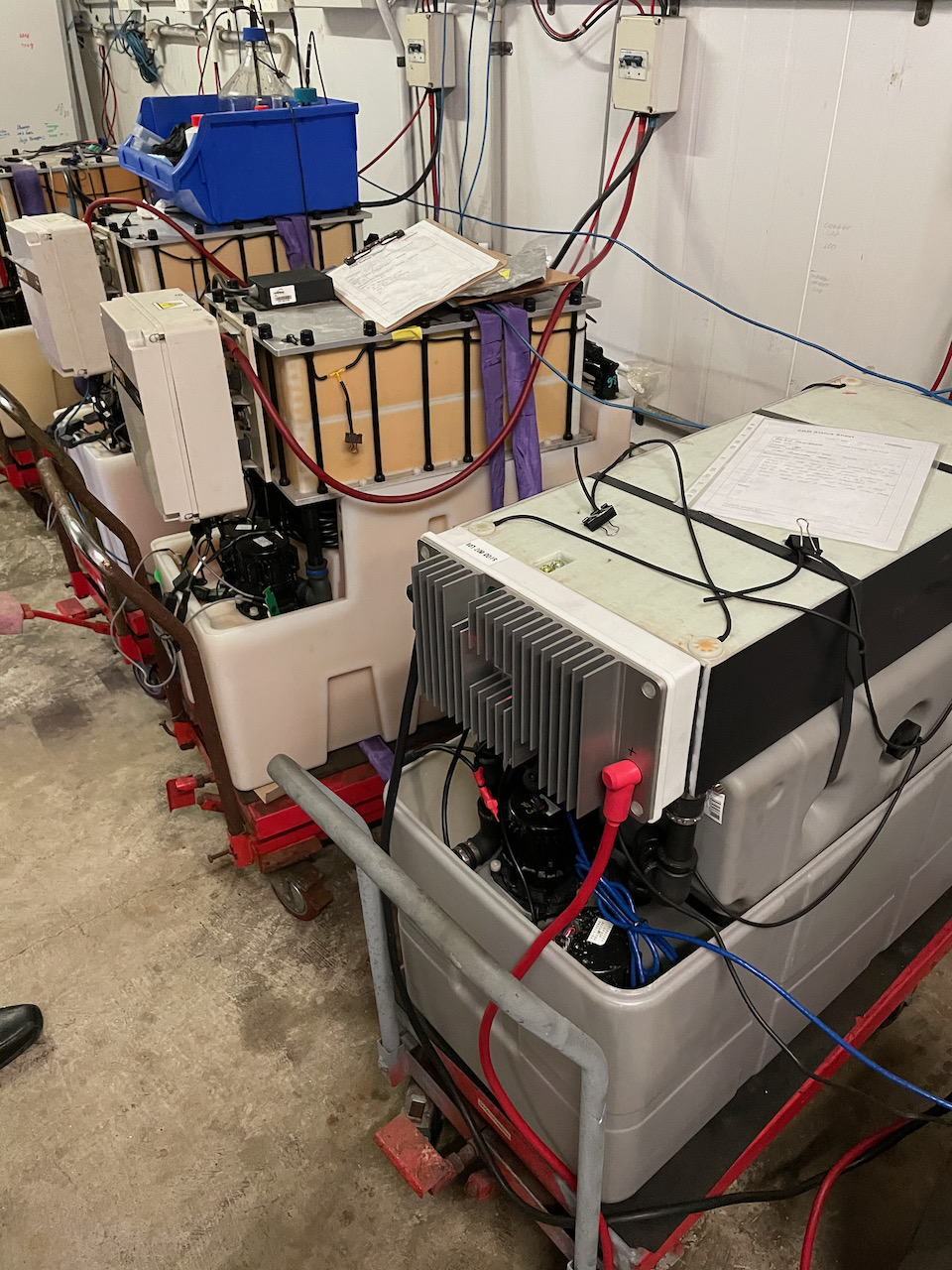
Flow Batteries
The system stores surplus energy in Redflow Zinc-Bromide flow batteries. These are a product that I have had a lot to do with over a long period (including as an investor in the company and as the the architect of the Redflow Battery Management System).
These batteries have a lot of advantages, compared to using Lithium batteries, for stationary energy storage applications such as this one.
Tasmania is interesting as a solar power deployment area, because it has the distinction (due to being a long way south!) of being the best place in Australia for solar production in summer, and the worst place in the country for solar production in winter!
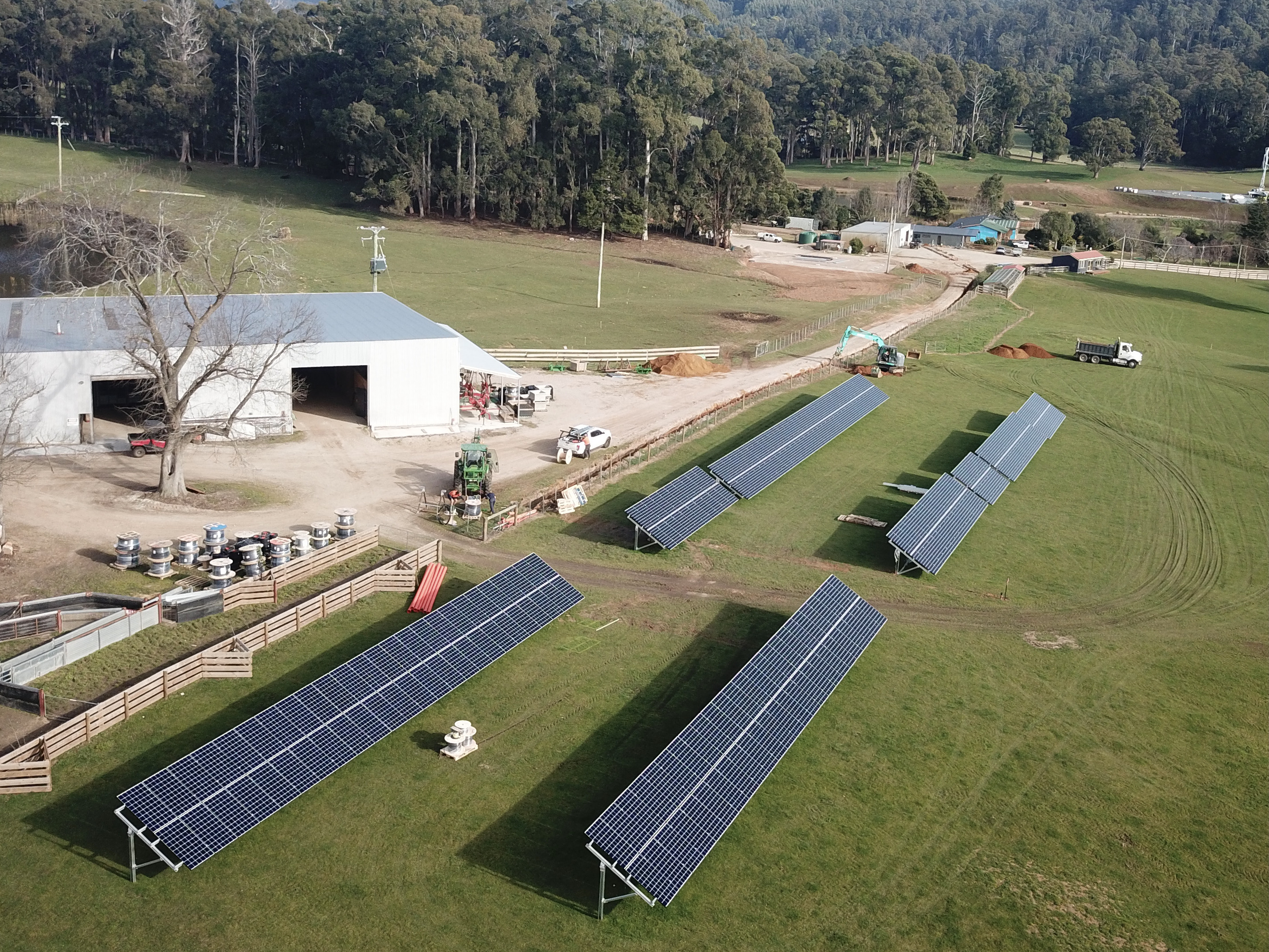
This was a key driver for the decision to deploy a relatively large solar array, with the aim of obtaining adequate overall performance in the winter months.
The large solar array is also a renewable transport fuel station!
We already run one Tesla Model S sedan, a Polaris ‘Ranger’ electric ATV, and an electric aircraft on the property.
Our plan is to progressively eliminate the use of diesel on the property entirely, by running electric 4WD vehicles, electric tractors, and electric excavators as they become available on the Australian market. The beauty of the large on-site solar array is that all of these vehicles can be charging directly from on-site solar generation when they are not being driven.
During this winter, we’ve observed that we typically manage to half-fill the battery array, and that it then lasts about half the night before grid energy is required.
That’s why we are now in the midst of doubling the size of the solar array. Once we have done so, we will have a system that (even in mid winter) can supply all of the on-site energy demands of the property on most days, without drawing any grid energy at all.
Of course, in summer, we’ll be exporting plenty of energy (and being paid to do so). Even with the relatively small feed-in tariff offered in Tasmania, the system generates a reasonable commercial return on the solar array investment in non-winter months.
Here are some (summer time) screen shots from the on-site control system and from the outstanding Victron VRM site data logging portal.
System Monitoring Example
On the image from the on-site Cerbo GX controller, you can see a point in time where the solar array was producing more than 90W, the battery array was mostly full and starting to roll back its charging rate, and plenty of that solar energy was also being exported to the grid.
The ‘System Overview’ and ‘Consumption’ charts show the outcome of all that sunshine…with the battery ending the day pretty much full, the site ran all night on ‘time shifted sunshine’ and started the following day half full, ready to be filled up once more.
We exported plenty of green energy to our neighbours and we used practically no inward grid energy at all.
Once we have doubled up the solar array size, we are looking forward to achieving a similar outcome on most winter days, not just during summer, along with exporting even more surplus green energy into the grid.
Once we have transitioned all the on-site vehicles to electric, our total export energy will diminish somewhat, but it will be more than offset by a $0.00 diesel fuel bill (and by zero CO2 and Diesel particulate emission from our on-site activities).
On-site Energy Efficiency
One thing that matters a great deal is to do the best you can in terms of energy consumption, not just energy generation and storage. To state the obvious: The less energy you need to use, the longer your battery lasts overnight.
All the houses on the farm are heated/cooled using heat pumps.
This is the most efficient way to do it, by far. It is often poorly understood just how much more efficient a heat pump is, compared to any other way to cool or heat something.
That’s simply because a heap pump doesn’t create the heat – rather, it moves heat energy in the outside environment into the house (or vice versa, to cool it). Typical values for the Coefficient of Performance (COP) – the ‘multiplier effect’ between kilowatts to run a heat pump and kilowatts of heat energy that can be moved – are of the order of 3-4 times. That literally means that 3-4 times as many kilowatts of heating or cooling are created than the number of kilowatts of energy put into the device to do it. By contrast, heating using an electrical ‘element’ has a COP of 1, meaning there is literally no multiplier effect at all.
Because we’re in Tasmania, and it does get cold in winter, we have put in a wonderful indulgence in the form of a Spa pool. These obviously need a fair bit of energy to keep the pool water hot, and we have done two things to minimise that energy draw.
First, we have used a Spa heat pump to do the hot water heating, which accesses that fantastic multiplier effect mentioned above. It means we are heating the water by just moving heat energy out of the surrounding air and into that water.
Second, we have installed an optional monitoring and control device so we can access the Spa and remotely control it. We can turn the heating off when we are leaving home, and we can then remotely turn the heating back on when we are heading back, so it is nice and hot when we arrive.
We have a third heat pump at our home, the one that heats our hot water. We are using a Sanden Heat Pump based hot water system that (also) performs really well.
On-site Energy Monitoring and Control
The key to optimising energy usage is to be able to actually measure it.
The Victron Energy Cerbo GX at the heart of the energy system monitors all aspects of our renewable power plant in detail (and uploads them for easy review to the no-extra-cost Victron Energy VRM portal). This gives us fantastic (and super detailed) visibility into energy generation, storage, and consumption on site.
However, we have a lot of separate buildings on the farm, and the key to understanding and optimising energy draw is to get deeper insight into which buildings are using energy and when.
To that end, we have installed many Carlo Gavazzi EM24 ethernet interfaced energy meters all around the site-wide underground power network. At each delivery point into a building, there is an ethernet-attached meter installed, so that energy usage can be narrowed down to each of these buildings with ease.
I am currently working on the design of an appropriate monitoring system that will draw this data in and use it to provide me with detailed analytics of where our energy is going on a per-building basis (and when!).
In terms of control we have deployed KNX based sensor and control devices in a variety of places around the property, and we plan to deploy much more of it. Over time, we’ll be able to dynamically control and optimise energy consumption in a variety of useful ways.
KNX is a whole separate story, but – in brief – its an extremely good way to implement building automation using a 30+ year old standardised protocol with full backwards compatibility for older devices and with support from over 500 hardware manufacturers. It allows for the successful deployment of totally ‘mix and match’ multi-vendor collection of the best devices for each desired building automation monitoring or control task.
We are continuing to learn as we go.
With the upcoming enhancements in site monitoring and control, we expect to deepen our understanding of where energy is being used, to (in turn) allow us to further optimise that usage, using techniques as simple as moving various high energy demands to run ‘under the solar curve’ wherever possible. These are the times when on-site energy usage is essentially ‘free’ (avoiding the ‘energy round trip’ via the battery, and leaving more battery capacity for energy demands that cannot be time-shifted overnight)
Summary
Overall, this system is performing extremely well, and we are extremely pleased with it.
When we have added even more solar, it will do even better.
The #1 tip – even in Tasmania – is clear: Just Add More Solar 🙂
The other big tip is to move your transport energy usage to electric.
The more electric vehicles we can deploy here over time (farm machinery as well as conventional cars), the better.
We’ll charge them (in the main) directly ‘under the solar curve’ and achieve a huge win-win in terms of both energy usage and carbon intensity.
As we keep learning and keep improving the monitoring and control systems… it will only get better from here.
This is a note to my American friends, many of whom have asked me how we are doing in Australia with the COVID-19 thing.
I felt that it would be simplest to write this down once instead of explaining it separately to every one of them…
In terms of COVID-19 Pandemic response, the USA is in the midst of snatching victory from the jaws of defeat.
The US experience has been one of significant failure during the early and mid term handling of the COVID-19 pandemic. Those failures, however, created powerful incentive for the US to become a global leader in the creation and delivery of vaccinations to its population.
The Australian experience is the exact opposite. Over here, we are busy snatching defeat from the jaws of victory!
Here is how the story has unfolded in Australia…
Both Australia and New Zealand used their ‘island nation’ situation to advantage.
Very early in the Pandemic period. Australia imposed (and continues to impose) severe rate limits and severe quarantine processes upon to those seeking to return from overseas.
Unusually, Australia also moved at the same time to prevent it own citizens from routinely leaving the country.
Australia then began an aggressive process of suppressing the virus where present in the community.
At the time, the official government line was the same as it was the world over, about ‘flattening the curve’. However there was a clear unofficial target to do far better than that, and against the odds, it happened:
Australia has achieved effective elimination of COVID-19 from the community.
This has been the result of enormous and sustained community engagement, coordinated and resourced through herculean efforts of by Australian state and territory governments.
State and territory public health teams operate annexed commercial hotels, renamed as ‘Quarantine Hotels’ (located, incredibly, in the centres of our major capital cities) to quarantine and process incoming international passengers at a heavily limited weekly rate.
Inevitably, COVID-19 outbreaks emerge out of those quarantine facilities. This usually (and predictably) happens as the result of cross-person infection within those facilities themselves, as these facilities were never designed for this purpose.
Each outbreak is then wrestled to the ground with yet another round of snap lockdowns. The state of Victoria has suffered the longest durations and the largest number of these lockdowns, and continues to do so:
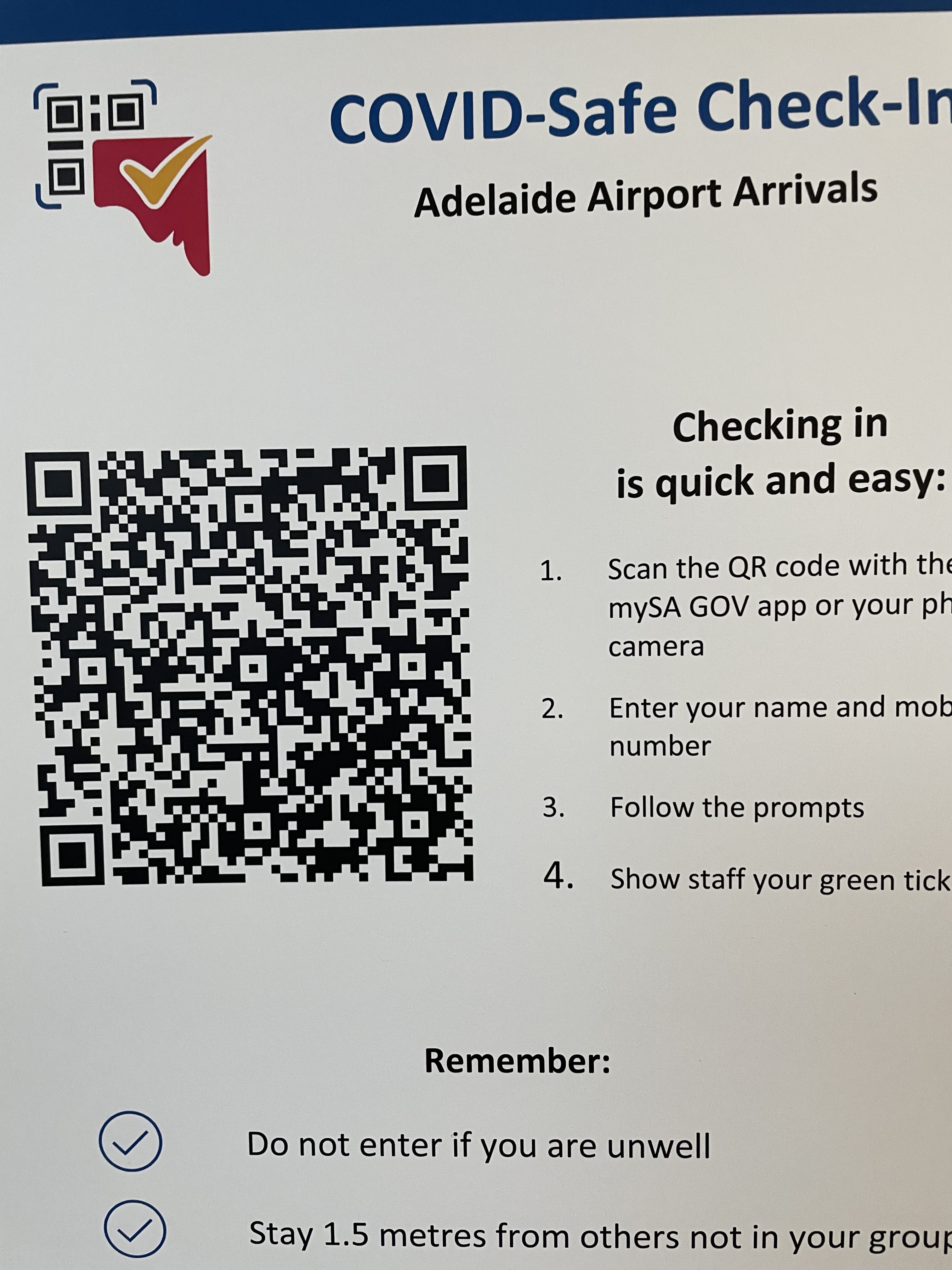
We have, as a society, agreed to reliably and voluntarily ‘sign in’ using QR codes at every public shop and venue, in order to leave an intentional digital breadcrumb trail of our movements.
This facilitates the rapid creation and update of site ‘exposure’ lists (sometimes hundreds of sites long) that are constructed and updated as a public health tool each time an outbreak occurs.
People whose movements intersect those lists obligingly get tested and self-isolate, almost without fail. In doing so, we collectively manage to grind every one of these outbreaks into dust (at considerable personal and societal cost).
As a society we have become trained in, and indeed expert at, a high stakes national game of ‘Whack-a-Mole’.
There has been a payoff for all of this effort. By and large, Australians now wander about in this country (most of the time) in a state of relative normalcy, living (most of the time) free of any COVID-19 at all.
It is clear, though, that we are living in the eye of a storm, and at face value we might be stuck here for a long time.
A major contributor to our situation is the fact that the Federal government in Australia continues to fail in its manifest duty to implement a rapid, high priority vaccination process across our entire community.
We originally had appropriate, aggressive, government vaccination delivery timeframes and targets.
Sadly, those targets were (badly) missed, before being just completely abandoned with barely a murmur.
Today the official government line is that – international experience not withstanding – this is “not a race” after all (!):
The manifestly botched Australian vaccination rollout generates the expectation that (if not resolved) Australia will have to keep playing ‘Whack-a-Mole” behind closed borders for at least another 18 months:
It is entirely possible to change this path and return Australians to the world community sooner than that.
We must improve and accelerate vaccination rates in Australia urgently.
We also need to get on the bandwagon as the MRNA vaccine producers gear up for making annual, variant-updated booster shots for next year, and the year after, and so on – just as we already do each year for the ‘seasonal flu’.
Doing this will require leadership, commitment, resourcing, simplified eligibility and access mechanisms, and a range of positive incentives (including differential access and travel rules for those who have been vaccinated and whose booster shot status is also maintained).
We can’t just hide away in our own private (national) Petri dish, telling ourselves that it is ‘not a race’.
The Redflow Zinc-Bromine Module (ZBM) is the smallest commercially available hybrid zinc-bromine flow battery in the world. The size of these 10kWh energy storage modules means they can be deployed in applications, such as telco tower sites, that were previously impossible to address with flow batteries, yet they can also scale to grid-level energy storage.
The Redflow ZBM is a convention-breaking energy storage machine. It can be thought of as a miniature, reversible, zinc electroplating machine made largely of recyclable plastic. The innovative Redflow battery design uses abundant and relatively cheap minerals in its electrolyte formulation. These attributes gives the product strong environmental credentials.
I recently spent some time at Redflow’s Brisbane headquarters taking a close look at the new Redflow Gen3 energy storage module. It is impressive to see just how far the Gen3 project has progressed in recent months and to appreciate the level of innovation it embodies.
Redflow has developed and optimised the design of its Gen3 battery in various stages during the past five years, incorporating knowledge and optimisations based on field deployment of the Gen2.5 product. The Gen3 battery utilises the advanced manufacturing capability developed by the company in its own dedicated factory and delivers a streamlined product designed for reliable and high volume production.
The Gen3 ZBM is slightly smaller, and yet delivers the same baseline performance specifications as the Gen2.5 module. Gen3 is designed to be an easy, drop-in replacement for the previous model in any customer application.
Redflow initiated Gen3 customer trials at the end of 2020 and also undertook further lab testing of key components and complete new Gen3 batteries. This has led to further design advances in Gen3 flow distribution, management of shunt currents and software optimisation. The current expectation is that Gen3 will be introduced into production around the end of 2021.
This is what a Redflow Gen3 ZBM looks like:
Redflow Gen3 ZBM
It is time to take a look under the hood… and the more you look, the more improvements become evident.
This is a photo of some Gen2.5 batteries, for comparison, sitting beside a Gen3 battery undergoing testing at Redflow:
Gen3 battery beside some Gen2.5 modules
There are many improvements in Gen3, all designed to reduce parts count and cost while also making the product easier to manufacture.
Single Stack vs Dual Stacks
The key Gen3 improvements are related to the “heart” the device, the electrode stack.
This unique battery stack design, materials set and manufacturing system are where the majority of the Intellectual Property, Patents and Know-How developed by Redflow over the past 10 years resides. The new Gen3 stack represents a major step forward for the company in all of these respects.
This new product implements a single 10kWh stack at the top of the Gen3, replacing a pair of 5kWh stacks on the Gen2.5 model. Having just one stack instead of two delivers an obvious long-term reliability benefit.
That single stack also lowers production cost and reduces complexity in physical, chemical, and electrical terms. Redflow has also revised the internal construction of the new stack, including the fluid flow paths and the stack surface itself, for simpler and faster manufacture.
Gen3 Stack electrode plate layers ready for final assembly
This single stack design eliminates the need to wire the two stacks together in parallel with an adaptor plate on the front of the stack, reducing parts count and complexity.
Moving to one stack also removes the requirement to bind the two stacks tightly together with large metal plates and long bolts. The Gen2.5 requires these relatively costly structures to maintain a consistent electrolyte fluid seal and to manage consistent electrolyte flow across both stacks. In Gen3, none of that is needed
The single new stack is simply strapped on to the top of the battery tanks, making it easier to replace the stack in the future, if required.
Because the stack is also a major cost item in the ZBM bill of materials and is also a critical path item in manufacturing time, the single stack delivers obvious and profound implications in terms of increased peak factory production rate and decreased overall production cost.
New Electronics Module (MMS)
The Module Management System (MMS) – the electronics box on the front of the battery stack – contains power-handling and control electronics which are run by an on-board device management computer.
The Gen3 MMS has been totally redesigned, delivering both short and long-term benefits.
The Gen2.5 battery MMS contains several separate circuit boards, due to more than a decade of incremental development. Gen3 puts them all on a single, redesigned, higher performance board.
The Gen3 battery MMS also has battery terminals on the front of the unit, rather than ‘behind’ the MMS, which makes electrical interfacing a lot easier.
The Gen3 design eliminates the separate “Energy Extraction Device” (EED) sold with Gen2.5 batteries by building that functionality into the MMS as a software-controlled element.
The new MMS costs much less to make and is far more powerful in terms of CPU and I/O capability.
Advanced current flow management and software-driven bidirectional DC/DC conversion circuitry allows for the development of improved MMS firmware to deliver new software-driven current control and voltage control features, along with other planned improvements. These will be rolled out to customers through in-field software updates via the Redflow Battery Management System (BMS).
Other improvements in the new MMS Include the use of solid-state circuit-switching hardware based on Field-Effect Transistors (FETs) to connect, disconnect and mediate energy flow into each ZBM, versus the use of three physical ‘Contactors’ inside the Gen2.5 MMS. This eliminates some expensive moving parts from the MMS by replacing them with devices that are not only faster but that have an essentially unlimited cycle life in this application.
Redesigned electrolyte tanks, pumps, and cooling structure
The ZBM has two electrolyte tanks, each with its own pump. The Gen2.5 uses a nested, ‘tank within a tank” arrangement that, while elegant, is quite complex and expensive to make. Gen2.5 tanks are also constructed with many sharp corners and a complex side-wall design, making high volume manufacturing even more challenging.
The new Gen3 tanks are quite different. This is a picture of the new tanks with pumps without any other parts installed. You can see that there is a new plastic formulation and that they feature distinctly rounded corners:
tank
This is all designed to optimise the tank for volume production. This design is easier to build and has an increased tolerance for variation between tanks during the manufacturing process. The new tanks are also arranged as a simple left-right pair – much simpler than the Gen2.5 nested tank structure, further improving ease of assembly.
The pumps have also changed. For historical reasons, the Gen2.5 pumps are actually 140 volt DC pumps that require a custom-designed voltage uplift circuit inside the MMS to drive them. The Gen3 pumps are 24 Volt DC pumps that can be more easily and efficiently driven from the MMS.
As part of the new Gen3 design, Redflow is also introducing a new cooling system using a new set of Filtering Polymeric Fibrous materials which will improve battery performance.
All up, the new tank cooling system and pump set represent a major improvement, designed, like the rest of Gen3, for repeatable high-volume manufacture at a lower production cost.
Purpose-built electrolyte ‘bund’
In many markets, energy storage devices that use fluid electrolyte in field deployments need to include a ‘bund’ – somewhere to catch and hold electrolyte fluid in the unlikely event of a fluid leak.
For the Gen3 battery Redflow has a new purpose-built bund. This is the plastic enclosure extending to about halfway up the battery on all sides, that is visible in the lab test photo above.
The intention is to ship Gen3 batteries with this bund included, saving installers the need to arrange and install a separate bund.
Gen3 Summary: Greater reliability, lower cost, faster production
The Gen3 module marks a major transition for Redflow.
Gen3 is designed for volume manufacture, with a design emphasis on fewer parts, greater ease of manufacture, and more compatibility with automated production techniques. By intent, this all leads to a lower production cost and greater long-term reliability.
These improvements benefit both Redflow and its customers as the company moves to ramp production volumes to meet the rapidly expanding global demand for scalable, sustainable and reliable energy storage.
Simon Hackett, Redflow System Integration Architect
introducing Pod Z
Redflow is in the midst of building a new “Pod” based energy storage architecture, with the first customer for that deployment also being its largest customer to date.
The story below includes a link to a short video about the new architecture Redflow has designed to support entry into the Grid-Scale energy storage market:
Redflow Pod Z grid-scale architecture using Trumpf HVDC modules
When we made that video, we hadn’t formally announced our partnership with TRUMPF Hüttinger, the company we’re working with to deliver this scalable architecture. A few days later, we were able to make that announcement:
Now we’ve made that announcement, I can explain how this nifty stuff works.
Here’s a photo of a Redflow Pod Z with some of the covers taken off:
Redflow Pod Z internal elements
On the left is the battery cabinet with one of four covers removed. This cube-shaped cabinet holds 16 x ZBM2 storage modules, 8 to a side.
Ventilation paths run inward at the base of each pod. Air flow then rises via a ‘cold aisle’ in the middle of the pod, proceeds through each ZBM2, and exits as warmer air via fans installed behind each cover door.
While the Redflow modules you can see here are the existing Redflow ‘Gen2.5’ devices, the upcoming Redflow Gen3 modules will also be a perfect fit, in both physical and electronic terms (and they are designed to be).
To the right is the electronics cabinet for the pod. Inside that cabinet, at the lower right, is a cluster of six Trumpf DC1010 units with a Trumpf System Controller.
The DC1010 module achieves something quite special. It is a bidirectional DC/DC converter that can shift voltage up to a very high ratio (around 15:1).
These modules are clustered together and driven in a unified manner via the the system controller.
On the the low-voltage side, these modules interface to a standard 48V telco standard voltage bus (compatible with Redflow ZBM2 modules).
In fact, beyond merely being ‘compatible’ with Redflow ZBM2’s – the Trumpf product has been specifically designed for flow batteries!
This product line has been created by Trumpf in response to the rising demand for the use of flow batteries in large energy systems.
Flow batteries are long duration, 100% depth-of-discharge, durable and high-temperature-tolerant workhorses. They compliment, rather than conflict, with the use of shorter-duration/higher-peak-output capability Lithium batteries.
Trumpf have developed this product line at a time and in a manner that is an ideal complement to Redflow energy storage modules, and that paves the way to create grid-scale hybrid deployments that include flow batteries.
Flow battery support in the DC1010 includes a capability to have the low voltage DC bus operating all the way down to zero volts. The units then support smoothly raising the voltage of a flow battery back up to its normal operating voltage range, smoothly ramping a current-limited/current-controlled energy supply to the modules, as part of commencing the next charge cycle.
The DC1010 modules are each rated at 200 Amps continuous on the low voltage bus, meaning that this cluster of six units can support up to 1200A on that bus.
In the first Pod Z configuration, Redflow has rated each pod at a nominal continuous energy throughput of 50kW.
The low voltage bus comes together on the left hand wall of the control cabinet. On that wall is a pair of DC bus-bars sandwiched around insulation layers, with built in ‘comb’ connectors that allow the battery circuit breakers to bolt straight on to the bus-bar.
A set of 48V bus cabling (visible on the left hand wall) fans out from the bus-bar to all 16 batteries on the left, and additional cables run down to the DC1010 cluster at the lower right.
On the high voltage side, the DC1010 units support a (software selectable) interface voltage in the 765-900 Volt range.
On the lower part of the rear wall, you can see the output side cables for the high voltage side. Those (small!!) wires run at circa 800 volts and come together to the high voltage interface terminals. At a 50kW power level, across six DC1010 units, at (say) 800V, the current being carried from each of the cluster modules is a mere 10 amps (50,000 / 6 / 800). This is why those wires are so small – because they really don’t need to be larger.
This is one half of the key to grid scale battery deployments. That high DC voltage means the total cable size – even for a DC bus visiting many Pods in parallel in a single site – really isn’t all that large.
The other half of how this architecture supports high scale deployments is the way that voltage management happens on that high voltage DC bus. We are operating these modules in a mode that Trumpf call ‘Voltage Static Mode’.
In this mode, the DC1010 cluster converts the variable ‘48V rail’ DC voltage into a fixed voltage outcome on the high voltage side. All the pods are programmed to have the same HVDC voltage when idle, and they are just wired together in parallel.
To connect the DC pods to an AC energy grid, third party AC inverter/chargers are used.
When those inverter/chargers wish to discharge or charge from the overall Pod array, they simply ‘pull’ or ‘push’ against that DC voltage. If the inverters try to discharge, they naturally draw the DC voltage down in the process. The external draw-down on the DC rail acts as an automatic signal to the DC1010’s to start to deliver output energy. The amount of energy they deliver is proportional to the voltage shift that the inverter/charger initiates on the DC bus.
In the reverse direction (array charging), the inverter/charger drives the DC voltage up, and the DC1010’s respond to this by moving energy from the DC rail into the Pods. Again, the amount of current that flows is controlled via the voltage shift that the inverter/charger initiates.
Here is a diagram showing this result, just to make it clear (taken from the Trumpf system documentation):
The deep point of this operating mode is that each pod acts like an ‘ideal’ battery on the HVDC side, that:
always sits at the ‘perfect’ voltage, waiting for work to do
can be wired to an arbitrary number of similar pods
can be wired to, and commanded by, inverter/chargers
… all using the chosen DC link voltage – and shifting of that voltage – as a command mechanism that requires no software interface and no real-time cluster synchronisation for it to work.
In the initial deployment site there will be twelve pods sitting in rows on concrete plinths, delivering 600kW throughput via 12×16 module pods, for a total of 192 Redflow ZBM2 modules on site:
Deployment arrangement using 12 x Pod Z modules
Meantime, back inside each Pod Z, the Redflow ZBM2 modules are coordinated and controlled by Redflow’s purpose designed BMS, operating in a cluster-friendly ‘Slave’ operating mode.
Each Pod Z’s BMS:
Drives the Redflow ZBM2 module operating cycle internally in each pod, including coordinated maintenance cycles for batteries at appropriate times
Actively controls the operation of the Trumpf equipment cluster using a newly developed Trumpf operating module in the BMS. This code sends continuous updates via MODBUS-TCP to the Trumpf cluster, keeping it informed about the present operating limits of that particular cluster of ZBM2 modules. The key parameters sent are the maximum charge capability, maximum discharge capability, and the target charge voltage for the ZBM2 cluster.
The BMS provides secure remote management access to the Trumpf system controller and manages the high level configuration of the pod (including setting the HVDC operating voltage and current limits in Voltage Static Mode).
The BMS also watches over the Trumpf cluster, monitoring and logging operating parameters including voltage, current, and three temperature measurement points inside each DC1010 cluster member
With each Pod Z being fully managed by its internal BMS, all that remains is to aggregate the status of all Pods together, for the benefit of, and the coordination of, the on-site inverter/chargers and on-site Microgrid controller.
A Redflow BMS operating in in ‘Master’ mode is interfaced over ethernet to all the downstream Slave BMS in each Pod Z that it watches over.
The Master BMS passes overall status data to the on-site microgrid controller. This includes System State of Charge, overall site charging and current discharging capacity, temperature, and state of health. This information is provided via industry standard CANBus ‘Smart Battery’ protocol, MODBUS-TCP, and/or JSON queries to the Master BMS.
Summary
The Redflow Pod Z architecture has been designed with, and around, the Trumpf ‘TruConvert’ DCDC power system architecture.
The combination creates a powerful, integrated high voltage energy storage system that can be scaled to an essentially unlimited extent.
The interface mechanisms being used allow the high energy, high voltage Pods to be parallel-wired without complex or difficult real-time synchronisation or balancing mechanisms. Instead, the software-mediated Trumpf cluster creates a ‘perfect’ battery voltage for every Pod, driving the simplest possible integration path for high scale site designers.
The Redflow BMS acts as a per-Pod orchestrator for the Redflow ZBM2 modules downstream, and as a coordination and control point for the Trumpf DCDC converters in each Pod, and passes aggregated energy storage status data upstream to the on-site master Microgrid controller.
This architecture plays to the strengths of all of the components concerned. It is is designed for reliability, redundancy, and scale.
The Ubiquiti UDM-Pro is a wonderful beast – everything you’d rationally want in a great, secure, high performance, feature-rich network router with a truly corporate grade feature set. In combination with Ubiquiti UniFI Switches and UniFI Access Points, the result is a capability to set up and run a network with something remarkably close to ‘the greatest of ease’.
The servers and services it makes available used to require days of head-scratching and a Unix command line. Instead, with this equipment, it takes a few hours and an iPhone App (for initial super-easy UDM-Pro configuration) and includes an excellent web interface (with secure remote access also available) for ongoing management.
For sites with lots of access points, it just doesn’t get easier than this – and the performance is excellent.
One thing I wanted to do with my (so far) two sites running this combination of equipment (UDM-Pro, UniFI switches and UniFI wireless Access Points) is to have a solid and seamless 4G 4G/LTE backup (Failover) path configured in and operating, for those times when the primary network connection is down.
Over time, I have cranked through quite a list of brands of both ethernet-to-4G gadgets, and (for a regional site I run), I had also cranked through lots of 4G diversity antennas, trying to find a good one.
In the hope of saving others the same expenditure of time, money, and experimentation, I am documenting the combination that is working (really well!) for me.
The barriers to a good experience in this regard are twofold. When it comes to a 4G-Ethernet ‘modem’, you need one that is fast, reliable, supports external diversity antennas, and (critically) supports ‘bridging’ of the 4G connection through to the ethernet port.
I’ve gone through a lot of (in hindsight) rubbish antennas before I found a good one, and I’ve also gone through a number of 4G/Ethernet routers that are either a bit rubbish and/or that insist on inserting their own layer 3 routing table into the data path, adding other /24 network range, more complexity, and becoming a barrier to direct end-to-end-access from the UDM-Pro to the 4G/LTE network provider.
The Parts List
Here are the devices that have worked (really well!) for me… after a trying a lot that did not work well or (in most cases) just did not work at all!
This model is available at Officeworks for A$249 (though I found you ‘had to ask’ – it was behind the front counter, not on the in-store shelving – perhaps because it is a relatively expensive and yet relatively small, hence steal-able box).
The unit has exactly what you need and nothing you don’t. There’s a LAN ethernet port (and a WAN one we don’t need to use for this application), and there is no WiFi (not needed, and just a distraction in practice to have it in there and to have to turn it off).
This unit takes a standard 4G/LTE SIM directly. This goes into little socket arrangement in the base of the unit is a touch non-obvious in terms of how to load and lock-in the SIM. That said, there is a little cardboard guide sheet stuck in the SIM slot to help you to work it out. You open the sliding cover, lay the SIM down on the pins in the box, close the cover and slide it up to lock it.
How to Insert a SIM into the LB 2120
I configured it at first with my Mac, using a USB-Ethernet dongle cabled directly to the unit with a (supplied) patch lead.
In terms of configuration: With a Telstra SIM installed, it was 100% instant plug-and-play, coming up initially on 192.168.5.1 and logged in using the password printed on the back of the box.
I did a firmware update (on general principles) – downloading via the LTE network to do it.
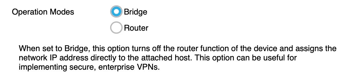
Then I simply switched the unit from router mode to ‘bridge’ mode. This is the key to a very simple life!
After rebooting into Bridge mode, the unit came up on my Mac with the Telstra 4G IP address attached directly to my Mac, fully automatically – exactly what I wanted to see. Zero configuration, and 192.168.x.x network is gone (so it is not, in any sense, ‘in the way’).
Ubiquiti SFP Ethernet Transceiver Module (for the WAN2 port)
When connecting the UDM-Pro to an Internet link, the primary port (designated “WAN(1)” must to be physical port #9. It cannot be any other port on the device (at least, not without behind-the-scenes internal configuration hackery I didn’t want or need to undertake).
Port 9 is a Gig-E port, so that is easily used to connect to (in my case) an Aussie Broadband NBN based Internet service.
In one site, I’m using an Aussie Broadband HFC connection which is direct plug-and-play – literally plug in a patch lead between port 9 on the UDM-Pro and the back of the Arris HFC modem supplied by NBNCo, and the Internet link ‘just works’… zero setup, zero complication. Just instant Internet. Win!
The WAN2 port (failover) port on the UDM-Pro is also a locked-in thing – it has to be Port 10.
As it happens, Port 10 is an SFP socket, not a Gig-E port.
What you need to buy to deal with that is a “Ubiquiti RJ45 – SFP Transceiver Module , SFP to RJ45 1G”
This module, available for $27 from Wireless4Now, plugs into the SFP socket on the UDM-Pro and turns that SFP socket into a standard RJ45 Gig-E port.
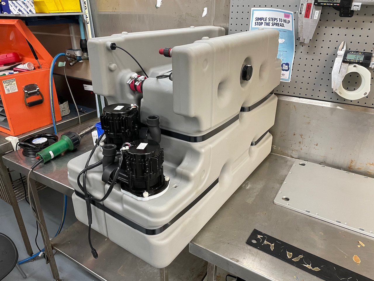
High Performance Outdoor 4G / LTE MIMO Antenna Set (optional)
In one site, in a city location, no external 4G antenna was needed with the LB2120 for entirely acceptable performance (30 megabits per second plus – entirely good enough for a failover link!)
In another (regional) site I’ve deployed this equipment into, however, the 4G tower site is several kilometres away (and the networking gear is in an outdoor metal cabinet). There is good line of sight, but at this sort of distance a simple omni-directional antenna doesn’t cut the mustard to get decent performance – its time to bring out the big guns.
After many false starts, I have found a specific antenna and cable combination that rocks. It is not cheap, but… boy does it work. It took my 4G site performance from 1 bar to 5 bars. It took the real world performance up from around 8-10 megabits per second into the 60-70 Megabit per second range (!).
4G MIMO Antenna
4G MIMO Antenna
The antenna kit that did the trick for me is a properly aligned (2 x 45 degree offset) pair of serious Yagi antennas, a suitable mount to achieve that alignment, a backhaul cable, and a 2 x TS9 adaptor tail set to suit the NetGear LB 2120’s on-board TS-9 sockets.
This setup is not cheap – running to a bit more than $600, from RFShop in Adelaide.
It is, however, absolutely worth it if you want to maximise your regional link performance, and the outcome, for me, was a dramatic improvement. This was achieved after multiple attempts with less ‘serious’ antenna sets (that either did nothing for me, or in some cases actually made the performance substantially worse)
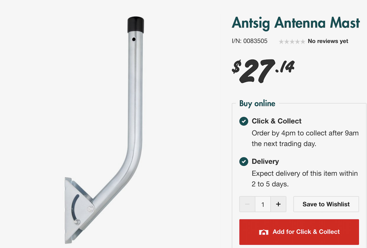
The one other item that was helpful in mounting that Yagi combination (which is quite heavy) was a short ‘TV’ antenna mounting bracket, that turned out to be perfect for the job, for another A$27 from Bunnings Aerospace 🙂
Configuration
Configuration of the failover path was trivial – due to using equipment that ‘just works’ 🙂
Indeed, it was totally plug-and-play. I just inserted the SFP module, plugged the Netgear device in (after first testing on my Mac as noted above), and that was it.
On the UniFI web interface, I selected the UDM-Pro and checked the characteristics for WAN2… bingo, already up and running!
Testing?
That is as simple as unplugging the primary (NBN) cable, observing that the Internet keeps right on going, and doing some speed tests to compare-and-contrast. When done, plug the NBN cable back in.
While nothing special in some other countries (like… New Zealand… let alone the USA), a better-than-100-Megabit Internet service at home has been an unattainable goal for me in the wilds of Adelaide, South Australia until now.
I have long had access to much faster speeds at the office, via path diverse gigabit fibre links that were installed back when I owned an Internet company, but not at home.
The companies who are giving the NBN a run for their money using fixed wireless services couldn’t help me, because I live in one of those leafy streets full of those tall things that leaves grow on. Our house has no radio line-of-sight to anywhere and no way to ‘fix’ that without the use of chainsaws. Not doing that.
At least, that’s how I felt about it before I’d done it.
I have since found that there are some genuine benefits beyond mere geek bragging rights.
Our home is in the HFC network footprint. Back in December 2013 (!) I penned a blog post about how HFC (while definitely not as good as pure fibre) was still capable of speeds well over 100 Megabits per second, and definitely a dramatic improvement over (sigh) FTTN.
I don’t think I was expecting it to be a seven year wait (!) but at last, here in 2020, I have finally got there, via the very same HFC box pictured in that 2013 blog post.
To my great chagrin, I’ve not been able to obtain those > 100 Meg speeds with the ISP I founded, Internode. It seems that Internode is a prisoner of the the TPG group’s apparent disinterest in keeping up with state-of-the-art NBN home Internet speeds.
The TPG group have ignored higher speed options on fixed-wireless for more than two years so far (and yes, I have asked – repeatedly), so I have little optimism for the group to return to the forefront in fixed line speeds on the NBN in general any time soon.
Time to change providers. This was a decision I was sad about because, well, I did start Internode!
The changeover process on the NBN fixed line network is incredibly smooth and simple – such a contrast to the complicated realm that Internode and others had to navigate when it came to switching between ADSL2+ DSLAM networks.
Online signup took just a few minutes. A little later the same day I got an SMS to say that I had a 250 Megabit Internet service running with Aussie Broadband.
There was no physical change to anything. I simply got an SMS message to say it was done, and without even resetting or logging into the router, the world got…faster.
In fact, I was a bit shocked at how fast it was:
Over-achieving on a ‘250’ megabit Aussie Broadband service
I’m used to real-world download speeds being lower than the ‘advertised’ line rate, because that advertised raw data rate typically includes TCP/IP packet overheads. By contrast, this service is achieving noticeably more than the advertised speed(!).
It is also amazingly consistent. At 8pm I tried again and instead of a 274 megabit per second speedtest result, I managed a ‘mere’ 273 Megabits per second. Indeed I am yet to see a speedtest result below 250.
“Nice upstream speed, kid…gonna miss it after the upgrade?”
One thing I am a bit sad about, and it is not Aussie Broadband’s fault, is the NBNCo decision to speed constrain the upstream direction on the NBN ‘250’ services to a mere 25 megabits per second. The NBNCo 100M service has a 40M upstream, and the loss of that faster upstream (and that’s what I used to have) real does peeve me a bit.
In my view, constraining the upload speed artificially is akin to a gangster charging ‘protection money’. This level of asymmetry (10:1) is a bit unreasonable when all of the underlying backhaul/CVC/etc links are full duplex (i.e. same-speed-both-ways) data paths, so the upstream pipes are mostly full of ‘air’. At the same ratio as the 100M NBNCo service, there really should be a 100M uplink speed on this service.
Anyway – it is what it is, and in this regard I am merely a paying customer.
(My Aussie Broadband Refer-A-Friend Code is 4549606 if you feel like doing the same thing and if you’d like a $50 credit when you sign up 🙂 )
Does it matter – can you tell the difference?
It turns out that you can.
Web browsing of even content-rich sites is now visibly ‘snappier’, which isn’t earth-shattering, but it is very nice.
It is (of course) in the downloading of large chunks of data that the speed difference really comes to the fore.
I found myself downloading the latest Mac OS X release, Catalina, that weighs in at around 12.5 Gigabytes (!). I hit the ‘Download’ button on the Mac App Store and went off to make a cup of coffee, being used to this sort of thing taking a fair old while, even on a 100M link.
I came back to the Mac a little over 5 minutes later and it was fully downloaded and waiting for me to hit the ‘start’ button to do the upgrade. I had to get the calculator out to decide if that was even possible…and it is. The speeds I am achieving equate to more than 2 Gigabytes per minute of achieved payload data rate. Mercy Sakes that is quick.
Another few hundred gigabytes of Dropbox folders needed to be synchronised over the Internet link into that same Mac. Sure, that took a few hours, but again it was way faster than it had ever happened before. A few hundred gigabytes.
Overall – I’m really loving this.
There is just no sense of conflict in usage by different household members, even when a few household members are are streaming high bandwidth 4K HDR content at the same time (and…they really do).
Even while that Mac was chugging away in a corner, re-synchronising hundreds of Gigabytes of Dropbox folders onto its onboard SSD, the Internet service remained just lightning-fast for everyday tasks.
The Weakest Link
Back in the ADSL2+ days at Internode, we would often have to chase down apparent Internet link speed issues that really turned out to be local (in-house) issues with WiFi base stations or other in-house network issues – even at a mere 10-20 megabits per second. The state of the art in routers and wifi at the time was a lot worse than it is today.
By contrast, the 270 megabit per second down speed test results I am consistently obtaining with my shiny new Aussie Broadband service are being achieved to a laptop over WiFi on the kitchen table – not even using a wired network port (!).
I have tried again on a wired port, just to see if it was different and it was exactly the same. Somewhere between my glass-half-full blog post about HFC in 2013 and now, the rest of the home network technology concerned has comprehensively ‘caught up’.
For interest, the on-site data path is:
A Ubiquiti EdgeRouter-X. This router is more than up to the speed task, rock solid and reliable, has automatic backup link failover, and the 5 port model I have at home comes in at under A$90. Incredible. This is a disruptive, excellent value device that is worthy of a separate review in its own right.
An old TP-Link rack-mount gigabit switch.
Multiple trusty Apple Airport Extreme base stations spread around the house, all connected on wired ethernet back to the central switch. Also well up to the task, but Apple don’t make ’em any more.
My (now) 3.5 year old MacBook Pro.
I’m intending to swap it all that out in a little while for a new set of Ubiquiti ‘UniFi’ series hardware (UDM-Pro, UniFi PoE switches and UniFi PoE Wireless Access Points).
I do not expect that change to create a speed gain. However, I deployed that full product set on our farm recently across a six site single mode fibre ring and – wow. That product set achieves everything on a complex site that used to take days of head-scratching with a Unix command line, and it turns it all into 10 minutes of point-and-click with a web browser. Again well deserving of a separate review sometime.
Conclusion
I am just loving the new 250 Megabit per second Internet service at home. Having spent most of my business career involved in the engineering of local, national and international many-gigabit-per-second networks, its nice to have something at home that – at last – feels like it is decently quick.
I’m hanging out for the full Gigabit service, though, on the happy day when NBNCo manage to get fibre down my street. Bring that on !
Today I experienced an ironic example of an Internet Service Provider (ISP) successfully avoiding any consideration of a well meaning (and simple!) suggestion to improve their offerings. It is ironic because the ISP concerned is Internode, the company I founded in 1991.
I meant well in trying to help them to improve their service offering, but all I wound up doing was falling down a funny / sad rabbit hole in terms of where those efforts landed me, as you will see.
I used what appeared to be the appropriate email address (found on this page):
This is what I sent (very lightly edited for additional clarity):
From: Simon Hackett
Subject: The absence of support for Fixed Wireless Plus is a strange
and unfortunate deficiencyDate: 17 October 2020 at 1:21:38 pm ACDT
To: customer-relations@internode.com.au
Hi guys,
I have a 25 Megabit fixed wireless service in Tasmania.
This is the fastest Fixed Wireless offering available from
Internode/iiNet/TPG.
Fully appreciate this sheets home to TPG decisions on how the NBN
Fixed Wireless service is operated - but - NBNCo introduced a new,
higher speed/best effort (up to 75/10) Fixed Wireless service a
long time ago (December 2018!).
I have tried repeatedly since to get my service upgraded to
support those higher speeds, but I have confirmed (on multiple
occasions) with the sales team that there is no plan to have
Internode able to offer those higher speeds… which is just crazy,
frankly.
I think I’ve given Internode at least a year to fix this - and it
isn’t getting fixed - that much is clear.
So - I’ve now given up and signed up with Aussie Broadband and as
of yesterday, I am indeed enjoying > 60 megabit per second
speeds on the same site with the same hardware and the performance
change is dramatic.
I will call the accounts team on Monday to cancel down the old
Internode services at the site concerned (snbs client ID is
<REDACTED>, for reference).
As the person who founded Internode, I have found it hugely
disappointing - indeed actually upsetting - to have had to do
this… but (sincerely) this ball (in terms of supporting fixed
wireless customers) has been comprehensively dropped on a long
term basis by the TPG group. Supporting the now-current Fixed
Wireless service offering and rolling existing customers over to
it would be trivial.
It beggars belief that this is not being done - but - well -
obviously it is not.
For the sake of not losing customers in Fixed Wireless over time
in this entirely avoidable manner, I would challenge you to
actually fix this. It won’t help me, any longer, but it would help
YOU (and your existing and future customers).
Yours sincerely,
Simon Hackett
Founder, Internode
I got an email reply promptly back from iiNet (note: not from Internode), which said:
Hi Simon

Would you mind providing your account number or mobile number for us to
assist you further.

Kind Regards
<REDACTED>
Case Manager
iiNet Customer Relations
I pointed out in reply that I had in fact already provided this information.
What floored me is what came back next:
Hello Simon,
Thank you for your email and I do apologize for the delayed response.
Please contact internode directly via the following link:
https://www.internode.on.net/contact/?dep=support
Their contact details are via the above website.
Warm Regards,
Customer Service Representative
iiNet Support
iiNet Limited, Locked bag 16, Cloisters Square WA 6850
ph: 13 22 58 fax: 1300 785 632
email:support@iinet.net.auweb:www.iinet.net.au
Um… excuse me?
Here’s the bottom line – I tried, but – having been taken on a complete runaround for my trouble, well, I’m outta there…
…and wondering why I gave them more than year to fail to address my original issue (as per my email above) before I left. Loyalty, I guess.
My Aussie Broadband ‘Refer-a-Friend’ code is 4549606 if you’re considering the same move, and it will get you (and me!) a $50 credit if you use it.
Thus far I’ve been highly impressed with the outcome, and I’ll have more to say about that later.
(Full Disclosure: I have also purchased some ASX:ABB shares after their recent IPO)
Ridge soaring is perhaps the simplest soaring lift method to understand. If the ambient wind strikes a perpendicular obstacle (like a ridge line), the air has no choice but to go… up.
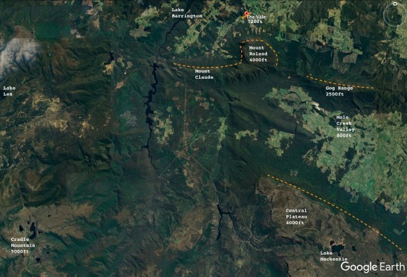
The 4000 foot Mount Roland, right beside the airfield, works really well for ridge soaring. The mountain is almost square, with sheer faces on the west, north and east sides. You can see this shape clearly on this Google Earth image of the local area:
(orange dotted lines show soarable ridge faces)
Annotated Google Earth image showing relevant features for soaring pilots
I’ve done a lot of ridge soaring on Mount Roland and on the ridge line extending immediately to the west, toward Mount Claude. However, until Day Three of this particular three day soaring exercise, I had never been over to the eastern ridge line – the Gog Range.
I took off and motored up in the Pipistrel Taurus Electro above the Gog Ranges, shut down the engine, and wafted down to the ridge line to give it a shot.
The wind was in the right direction but wasn’t very strong, so I couldn’t get much above ridge-top height, but I had no problems in maintaining that height, while flying end to end along the Gog Ranges ‘at will’, with an armchair view, watching the world go by 🙂
After a few passes back and forth along the full length of the ridge, I recorded a short video of the experience:
The beeping sound in the video is the sound of the “Audio Vario”. It is a good sound to hear when gliding.
The Audio Vario is a standard piece of gliding instrumentation that converts aircraft rate-of-climb into a tone sequence that becomes more urgent/higher pitched as the climb rate increases. The tone falls away entirely when you are not in lift. This sound lets a soaring pilot keep their eyes outside the cockpit, while using their ears to gauge their soaring performance.
The Gog Range is around 2500 feet high, and the terrain and the forest are really quite pretty. Ridge soaring really allows the opportunity to see it all ‘up close and personal’.
Interestingly, the Skysight ridge lift prediction (below) didn’t highlight the Gog Range, but it did show good ridge conditions on the edge of the Central Plateau itself – parallel and to the south of the Gog Range. It was that prediction that gave me the impetus to try the nearer, smaller Gog Range line.
The Central Plateau is a much higher, much more sheer, face – but it is also somewhat further away (with a long motor run back into wind to get home from it). That is something to try on another day.
Here is how the ridge looked, from the far (eastern) end, looking back toward Mount Roland in the distance:
First visit to the Gog Range in ridge conditions
Skysight Ridge Lift Prediction
This ridge flight in the Taurus Electro capped off three excellent days, experiencing three different weather systems and three different sorts of soaring technique, all in the same place.
Thermals are columns of rising hot air, driven by the sun differentially heating the ground. When there is sufficient moisture in the atmosphere, that rising air condenses at the top of the thermal to form a Cumulous cloud (or ‘Cu’).
Cumulous clouds are the classic fluffy white clouds often seen on a sunny day. These clouds showing a glider pilot the top of where a thermal is (or where it was – the lift under them tends to ‘cycle’ on and off over time).
Thermals can exist whether the Cu clouds are there as indicators of it or not. The gliding term for the Cu cloud right above you is a “Near Cu”. The term for the even better looking Cu Cloud that is just too far away to reach is a “Far Cu”.
Covering ground on a Thermal day involves circling slowly and tightly in the core of the rising air, gaining height, until the thermal starts to weaken. Then it is time to set sail for your intended destination, optimising your cruising performance by slowing down in lift and speeding up in ‘sink’ (a technique called ‘Dolphin Soaring’). If you get low again, it is time to find another thermal.
Australia is a great place to fly gliders in general. In the arid areas of the mainland it is possible to achieve quite spectacular soaring distances in the middle of summer. How far can you go? Just take a look at the current Australian Distance Records.
Back in Tasmania, on Day Two of Three, the wind had moderated and the day was several degrees warmer. The Skysight weather model indicated that there would be thermals in the middle of the day rising to 5500 feet or so, which is easily high enough to have a very fine time going gliding.
We set off in the Pipistrel Taurus Electro to explore those thermals and found that they were big, wide and gentle (not always the case!), and that the intermediate sink zones were also quite moderate.
Gabe and I wound up reaching around 6000 feet (very much in accordance with the prediction) over the very same valley that we had wave soared across the day before. The snow on the Central Plateau from the previous day had already started to melt.
We had a lovely time of it, just wafting about the neighbourhood, and the living was easy. Indeed, as is often the case on a good thermalling day – by late in the afternoon it seemed hard to go down 🙂
Here are some pictures from Day Two:
Mount Roland from just above the summit
High Altitude Headgear
Mount Roland looks dramatic from any angle
Near Mole Creek with Mt Roland (left) and Gog Range (right) in the distance
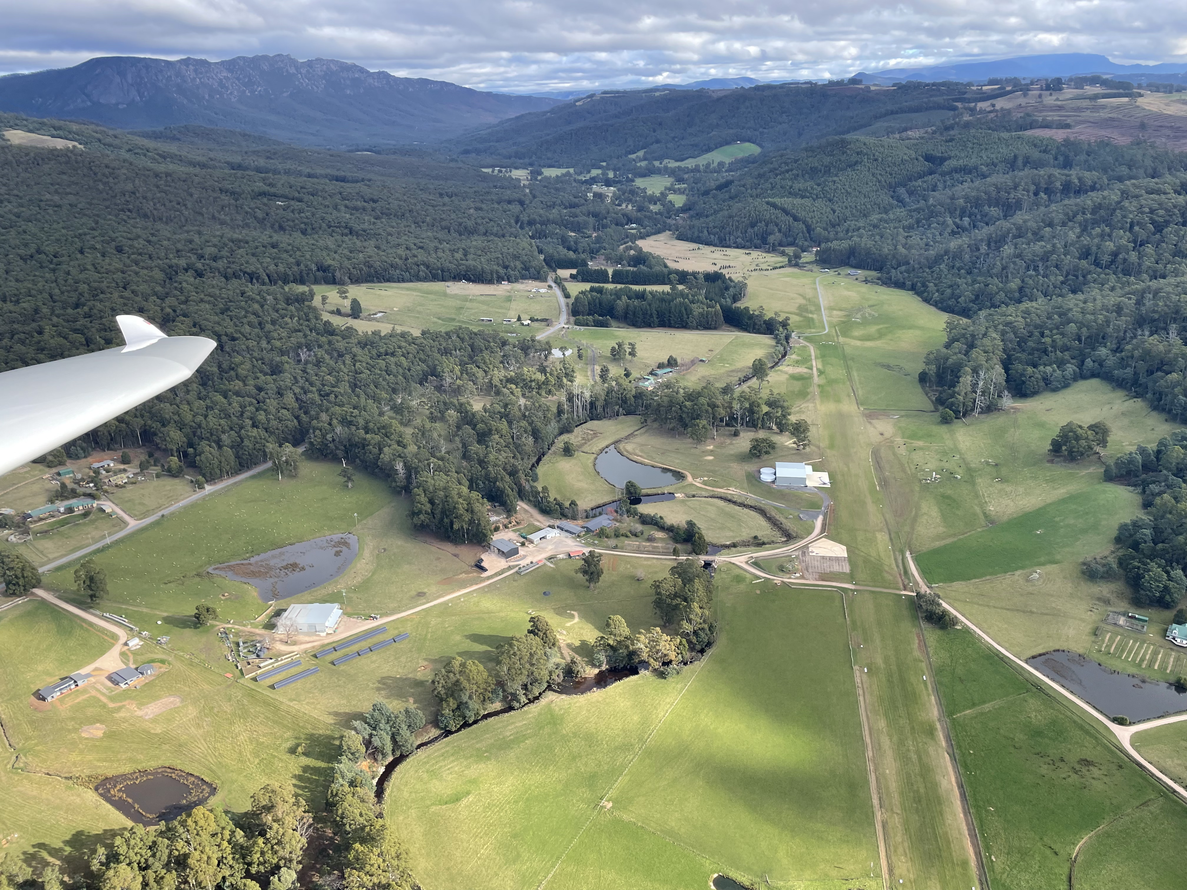
The Vale Airfield
Skysight Thermal Model
Going in Circles: Thermals to 6000 feet
In the next post – on day three – I had a chance to use yet another soaring technique – Ridge Soaring.


 iiNet Limited, Locked bag 16, Cloisters Square WA 6850
ph: 13 22 58 fax: 1300 785 632
email:
iiNet Limited, Locked bag 16, Cloisters Square WA 6850
ph: 13 22 58 fax: 1300 785 632
email: 


You must be logged in to post a comment.